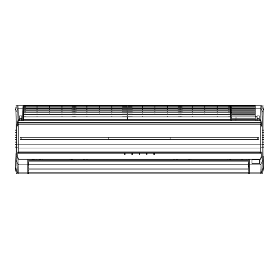
Fujitsu AWYZ14LBC Service Manual
Hide thumbs
Also See for AWYZ14LBC:
- Operating manual (26 pages) ,
- Service instruction (26 pages) ,
- Service manual (14 pages)
Advertisement
Table of Contents
SPLIT TYPE
ROOM AIR CONDITIONER
CEILING WALL TYPE
INVERTER
Indoor unit
Outdoor unit
AWYZ14LBC
AOYZ14LBC
AWYZ14LBC
AOYZ14LBL
AWYZ18LBC
AOYZ18LBC
AWYZ18LBC
AOYZ18LBL
C ONT EN T S
SPECIFICATIONS . . . . . . . . . . . . . . . . . . .
OUTLINE AND DIMENSIONS . . . . . . . . .
REFRIGERANT SYSTEM DIAGRAM . . . .
CIRCUIT DIAGRAM . . . . . . . . . . . . . . . . .
INDOOR PCB CIRCUIT DIAGRAM . . . . .
ERROR CONTENTS . . . . . . . . . . . . . . . .
DISASSEMBLY ILLUSTRATION. . . . . . .
PARTS LIST . . . . . . . . . . . . . . . . . . . . . .
1
2
3
4
5
8
10
11
15
Advertisement
Table of Contents

Summary of Contents for Fujitsu AWYZ14LBC
-
Page 1: Table Of Contents
SPLIT TYPE ROOM AIR CONDITIONER CEILING WALL TYPE INVERTER Indoor unit Outdoor unit AWYZ14LBC AOYZ14LBC AWYZ14LBC AOYZ14LBL AWYZ18LBC AOYZ18LBC AWYZ18LBC AOYZ18LBL C ONT EN T S SPECIFICATIONS .... -
Page 2: Specifications
SPECIF IC AT IONS ELECTRICAL DATA COMPRESSOR AND REFRIGERANT Cooling and Heat-pump heating TYPE Hermetic type, Inverter, TYPE Three phase INDOOR UNIT AWYZ14LBC AWYZ18LBC Induction motor, Rotary OUTDOOR UNIT AOYZ14LB_ AOYZ18LB_ DISCRIMINATION 808 - 907 - 80 COOLING CAPACITY 4.2 kW 5.2 kW... -
Page 3: Outline And Dimensions
D I ME N S IO N S Unit : mm INDOOR UNIT OUTDOOR UNIT 2006.01.12... -
Page 4: Refrigerant System Diagram
R E F R I GE R ANT S Y S T E M DI AGRA M Heat exchanger ( INDOOR ) Heat exchanger B 3-Way Valve 2-Way Valve ( INDOOR ) Muffler Muffler Receiver Compressor 4-Way Valve Strainer Accumulator Heat exchanger ( OUTDOOR ) Strainer... -
Page 5: Circuit Diagram
CIR C UI T DI A GRA M AIR FILTER (LEFT) SWITCH (LEFT) TERMAL INDOOR UNIT FUSE 102 AIR FILTER (RIGHT) SWITCH INDICATOR PCB (RIGHT) CN208 TERMAL FUSE 102 CONNECTOR (RED) BROWN WHITE WHITE ORANGE CN201 CN200 CN203 CN202 CN204 WHITE WHITE WHITE... - Page 8 I N DI C A T O R P CB Models : AWYZ14LBC AWYZ18LBC 2005.12.27...
-
Page 11: Error Contents
ERRO R CO NTE NTS Display Error Operation Error Timer LED 2 flash Serial signal (reverse) error, at operation start up 3 flash Serial signal (reverse) error, during operation Serial signal error 4 flash Serial signal (forward) error, at operation start up 5 flash Serial signal (forward) error, during operation 2 flash... -
Page 12: Disassembly Illustration
DISASSE MB LY I LLUSTRA TIO N INDOOR UNIT 2010.09.06... - Page 13 INDOOR UNIT 2010.09.06...
- Page 14 INDOOR UNIT 2010.09.06...
-
Page 16: Parts List
P A RT S L I S T INDOOR UNIT Ref. Description Ref. Description Part number Part number Remote Control 9314157028 Receiver Case 9313842017 Remote Control Holder 9312947010 Power Cord Assy 9900339029 Bracket Panel 9312011018 Display Assy 9705808027 Front Panel Total Assy 9313882150 Indicator PCB 9705809024... - Page 17 OUTDOOR UNIT Ref. Description Part number Top Panel Assy 9309230057 Cabinet Sub Assy 9314809040 Blow Grill 9308884015 Cabinet Right Assy 9309236011 Fan Ring 9308885012 Grip 9308880017 Switch Cover Assy 9309237025 Protective Net 9315319012 4-way Valve 9970036019 Pulse Motor Valve Assy 9314444012 Condenser Assy 9314040023...
- Page 18 ACC E S S O RIE S The following installation accessories are supplied. Use them as required. Name and Shape Q'ty Name and Shape Q'ty Drain pipe Wall hook bracket 9303029022 9312011018 Cloth tape Remote control 9308117007 Tapping screw (big) 9315029010 Battery 0700076046...
- Page 19 0512G2969...


