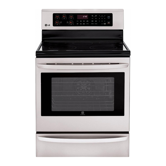
LG LRE3025ST Installation Manual
Electric range
Hide thumbs
Also See for LRE3025ST:
- Owner's manual (89 pages) ,
- Installation manual (13 pages) ,
- Specification (2 pages)
Table of Contents
Advertisement
Quick Links
Advertisement
Table of Contents

Summary of Contents for LG LRE3025ST
- Page 1 INSTALLATION MANUAL ELECTRIC RANGE Please read these instructions thoroughly before installing and operating the range. LRE3025ST LRE3083SW LDE3037SW LDE3031ST LRE3085ST LRE3021ST LDE3035ST LSE3092ST LRE3083ST LDE3037ST LDE3035SB LSE3392ST LRE3083SB LDE3037SB LDE3035SW LSE3090ST www.lg.com...
-
Page 2: Table Of Contents
TABLE OF CONTENTS TABLE OF CONTENTS SAFETY 3 Before You Begin 3 Important Safety Instructions 5 Prepare to Install the Range PREPARE TO INSTALL RANGE 6 Installation Drawings ELECTRICAL CONNECTIONS 8 Electrical Connection Requirements 8 Connect Range Cord 10 3-Wire Connection With a Power Supply Cord 4-Wire Connection With a Power Supply Cord 3-Wire Connection: Conduit 12 4-Wire Connection: Conduit... -
Page 3: Safety
Remove all tape and packing materials before using the range. Dispose of all plastic bags after unpacking the range. Never allow children to play with packing materials. You can download the installation and owner’s manual at: http://www.lg.com. IMPORTANT SAFETY INSTRUCTIONS Read and follow all instructions before using your oven to prevent the risk of fire, electric shock, personal injury, or damage when using the range. - Page 4 SAFETY WARNING • Power supply cord and plug should not be modified. If it will not fit the outlet, have a proper outlet Installed by a qualified electrician. • Using an extension cord to connect the power is prohibited. The way to connect the power cord and plug directly is strongly recommended.
-
Page 5: Prepare To Install The Range
SAFETY PREPARE TO INSTALL THE RANGE WARNING • The information in this manual should be TOOLS NEEDED followed exactly. - A fire or electrical shock may result causing property damage, personal injury or death. Phillips Screwdriver Level WARNING Flat-blade Adjustable Wrench Tip - Over Hazard Screwdriver A child or adult can tip the range and be... -
Page 6: Prepare To Install Range
PREPARE TO INSTALL THE RANGE INSTALLATION DRAWINGS NOTE SAVE FOR THE USE OF THE LOCAL ELECTRICAL INSPECTOR CAUTION CLEARANCES AND DIMENSIONS (Figure 1) To install range refer to the following Figure 1. • Cabinet storage space located above the For installation in CANADA, a Free-standing range surface units should be avoided. - Page 7 PREPARE TO INSTALL THE RANGE For model : LSE Series 24” (60.9cm) A = 30”(76.2 cm) For U.S.A = 30”(76.2 cm) ~ 31”(78.7 cm) For CANADA FIGURE 1 FIGURE 2 For model : LDE Series Cabinet opening Wall Center Cabinet 6”...
-
Page 8: Electrical Connections
ELECTRICAL CONNECTIONS ELECTRICAL CONNECTION CONNECT RANGE CORD REQUIREMENTS The Rear Access cover must be removed. Loosen the two screws with a screwdriver. The terminal block will then be This appliance must be installed and grounded on a accessible. branch circuit by a qualified technician in accordance with the National Electrical code ANSI/NFPA NO. - Page 9 ELECTRICAL CONNECTIONS The Cord/Conduit connection plate is used for the WARNING (LDE series only) installation of power cord or conduit. For power cord, • You never remove the protec tion cover install it with the connection plate as INSTALLED. For covering the rear of lower oven.
-
Page 10: Wire Connection With A Power Supply Cord
ELECTRICAL CONNECTIONS 3-WIRE CONNECTION WITH A POWER SUPPLY CORD WARNING • The middle (neutral or ground) wire, which is white, of a 3 wire power cord or a 3 wire Conduit conduit has to be connected to the middle connection Cord strain relief plate post of the main terminal block. -
Page 11: 1 4-Wire Connection With A Power Supply Cord
ELECTRICAL CONNECTIONS 4-WIRE CONNECTION WITH 3-WIRE CONNECTION: CONDUIT A POWER SUPPLY CORD Install the conduit as follows: WARNING Remove the Conduit connection plate from the rear of oven and rotate it as shown in Figure 5. The conduit hole • Only a 4-conductor power-supply cord kit rated ") must be used. -
Page 12: Wire Connection: Conduit
ELECTRICAL CONNECTIONS 4-WIRE CONNECTION: CONDUIT WARNING 4-wire connection • The middle (neutral) wire, which is white, of the Black White Red power cord or 4-wire conduit has to be connected Terminal block to the middle post of the main terminal block. The other two wires of the power cord or conduit Ground strap... -
Page 13: Install The Range
INSTALL THE RANGE ANTI-TIP DEVICE INSTALLATION First check direction . level After check direction . WARNING If the level doesn’t show level on the rack, adjust Tip - Over Hazard the leveling legs with a A child or adult can tip the range and be wrench.


