Sign In
Upload
Manuals
Brands
Hewlett Packard Manuals
Portable Generator
83640B
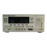
User Manuals: Hewlett Packard 83640B Sweep Signal Generator
Manuals and User Guides for Hewlett Packard 83640B Sweep Signal Generator. We have
1
Hewlett Packard 83640B Sweep Signal Generator manual available for free PDF download: User Manual
HP 83640B User Manual (496 pages)
Swept Signal Generator, Including Options 001, 002, 004, 006, and 008
Brand:
HP
| Category:
Portable Generator
| Size: 5 MB
Table of Contents
Table of Contents
13
Getting Started
30
What Is in this Chapter
30
How to Use this Chapter
31
Equipment Used in Examples
31
Introducing the HP 8360 B-Series Swept Signal Generators
32
Display Area
33
Entry Area
34
CW Operation and Start/Stop Frequency Sweep
35
CW Operation
35
Start/Stop Frequency Sweep
35
Center Frequency/Span Operation
37
Power Level and Sweep Time Operation
39
Power Level Operation
39
Sweep Time Operation
39
Continuous, Single, and Manual Sweep Operation
41
Marker Operation
43
Saving and Recalling an Instrument State
45
Power Sweep and Power Slope Operation
47
Power Sweep Operation
47
Power Slope Operation
48
Getting Started Advanced
49
Externally Leveling the Swept Signal Generator
51
Leveling with Detectors/Couplers /Splitters
51
External Leveling Used with the Optional Step Attenuator
54
Leveling with Power Meters
55
Leveling with MM-Wave Source Modules
56
Working with Mixers/Reverse Power Effects
58
Working with Spectrum Analyzers/Reverse Power Effects
60
Optimizing Swept Signal Generator Performance
61
Creating and Applying the User Flatness Correction Array
61
Creating a User Flatness Array Automatically, Example 1
62
Creating a User Flatness Array, Example 2
64
Swept MM-Wave Measurement with Arbitrary Correction Frequencies, Example 3
67
Scalar Analysis Measurement with User Flatness Corrections, Example 4
71
Using Detector Calibration
75
Using the Tracking Feature
77
Peaking
77
Tracking
77
ALC Bandwidth Selection
78
Using Step Sweep
79
Creating and Using a Frequency List
80
Using the Security Features
81
Changing the Preset Parameters
82
Getting Started Programming
83
HP-IB General Information
84
Interconnecting Cables
84
Instrument Addresses
84
HP-IB Instrument Nomenclature
84
Controller
84
Listener
84
Talker
84
Programming the Swept Signal Generator
84
HP-IB Command Statements
85
Abort
85
Local Lockout
86
Remote
86
Clear
87
Local
87
Output
88
Enter
89
Getting Started with SCPI
91
Definitions of Terms
91
Standard Notation
92
Angle Brackets
92
Command Mnemonics
92
How to Use Examples
92
Command Examples
92
Response Examples
93
Essentials for Beginners
94
Program and Response Messages
94
Forgiving Listening and Precise Talking
94
Types of Commands
95
Subsystem Command Trees
96
Paths through the Command Tree
96
The Command Tree Structure
96
Subsystem Command Tables
99
Reading the Command Table
99
Implied Commands
100
More about Commands
100
Optional Parameters
100
Program Message Examples
100
Query and Event Commands
100
Numeric Parameters
101
Parameter Types
101
Extended Numeric Parameters
102
Boolean Parameters
103
Discrete Parameters
103
Reading Instrument Errors
104
Example Programs
105
Description
105
Example Program
105
Program Listing
105
Program Comments
106
Details of Commands and Responses
108
In this Subsection
108
Program Message Syntax
108
Common Command Syntax
109
Subsystem Command Syntax
109
Response Message Syntax
110
SCPI Data Types
111
Extended Numeric Parameters
111
Numeric Parameters
111
Parameter Types
111
Boolean Parameters
113
Discrete Parameters
113
Real Response Data
113
Response Data Types
113
Discrete Response Data
114
Integer Response Data
114
String Response Data
114
Programming Typical Measurements
115
In this Subsection
115
Using the Example Programs
115
Use of the Command Tables
116
HP-IB Check, Example Program
118
Program Comments
118
Local Lockout Demonstration, Example Program
119
Example Program 8
119
Programming the Status System
134
In this Subsection
134
General Status Register Model
134
Condition Register
134
An Example Sequence
135
Enable Register
135
Event Register
135
Transition Filter
135
Programming the Trigger System
137
In this Subsection
137
Generalized Trigger Model
137
Overview
137
Details of Trigger States
138
Inside the Idle State
139
Inside the Initiate State
139
Inside Event Detection States
140
Inside the Sequence Operation State
142
Common Trigger Configurations
143
The INIT Configuration
143
The TRIG Configuration
144
Description of Triggering in the HP 8360 B-Series Swept Signal Generators
145
Advanced Trigger Configurations
146
Trigger Keyword Definitions
146
Abort
146
Immediate
146
Odelay
146
Source
147
Related Documents
148
The International Institute of Electrical and Electronics Engineers
148
Hewlett-Packard Company
148
How to Use this Chapter
149
Address
150
Adrs Menu
150
AM Menu
163
AM On/Off la Db/V
164
Aman/Off Ext
167
Amp1 Markers
167
Analyzerstatus Register
169
Arrow Keys
171
Blank Disp
178
Copy List
190
Corpair Disable
190
Coupling Factor
191
CW/CF Coupled
192
Dblr Amp Menu
193
Deep am
194
Delay Menu
194
Delete Menu
195
Delete All
195
Delete Current
196
Delete Undef
197
Delta Marker
197
Delta Mkr Ref
198
Disp Status
199
Doubler Amp Mode AUTO
200
Doubler Amp Mode Aff
202
Dwell Coupled
202
Entercorr
204
Enter List Dwell
206
Enter List Freq
206
Enter List Offset
207
Entrykeys
207
Entry on off
208
Extdet Cal
208
Fault Menu
209
Fault Info T
209
Fault Info 1
210
Fault Info 2
211
Fltness Menu
213
Fltness on off
218
FM Coupling 1Ookhz
219
FM Coupling DC
219
Fmmenu
220
FM On/Off DC
221
FM On/Off Int
223
Freqcai Menu
224
Freq Follow
224
Frequency
225
Freqmult
225
Freq Offset
225
Internal am Depth
232
Internal am Rate
233
Internal am Waveform Noise
233
Internal am Waveform Ramp
234
Internal am Waveform Sine
234
Internal am Waveform Square
235
Internal am Waveform Triangle
235
Internal FM Deviation
236
Internal FM Rate
236
Internal FM Waveform Noise
237
Internal FM Waveform Ramp
237
Internal FM Waveform Sine
238
Internal FM Waveform Square
238
Internal FM Waveform Triangle
239
Internal Menu
239
Internal Pulse Generator Period
240
Internal Pulse Generator Rate
241
Internal Pulse Generator Width
241
Internal Pulse Mode Auto
242
Internal Pulse Mode Gate
242
Internal Pulse Mode Trigger
243
Invert Input
243
Leveling Modenormal
245
Leveling Modesearch
245
Leveling Pointextdet
246
Leveling Pointintrnl
246
Leveling Pointmodule
247
Leveling Pointpwrmtr
248
Lineswitch
248
Listmenu
249
List Mode Pt Trighuto
251
List Mode Pt Trigbus
252
List Mode Pt Trigext
252
(Local
253
Manual Sweep
254
Markerml
257
Markerm2
258
Markerm3
258
Markerm4
259
Markerm5
259
Markers All off
260
Measure Corr All
260
Measure Corr Current
261
Measure Corr Undef
261
Meter Adrs
262
Meter On/Off FM
263
Modout On/Off am
264
Modulation
264
Amplitude Modulation
267
FM Modulation
270
Pulse Modulation
272
Module Menu
276
I {Odule Select AUTO
276
Module Select Front
277
Module Select None
278
Module Select Rear
279
Monitor Menu
279
More N/M
280
Mtr Meas Menu
281
Peak RF Always
282
Tracking Menu
282
Peakrfonce
283
Power Level
283
Power(K
283
Power Offset
287
Power Slope
288
Power Sweep
289
(Preset
290
Preset Mode Factory
291
Preset Mode User
292
Printer Adrs
292
Programming Language Analyzr
294
Programming Language SCPI
295
Pt Trig Menu
296
Pulse Delay Normal
297
Pulse Delay Trig'D
297
Pulse Menu
298
Pulse Menu
299
Pulse On/Offintrnl
300
Pulse Onfoffextrnl
300
Pulse Period
302
Pulse Rate
302
Pulse Rise Timeauto
303
Pulse Rise Timefast
303
Pulse Rise Timeslow
304
Pulse Width
304
Pwrmtr Range
305
Rotary Knob
307
Save User Preset
309
Savelock
309
SCPI Conformanceinformation
310
:Start
311
Trigout Delay
379
Uncoupl Atten
390
Unlock Info
390
Up/Dn Size CW
391
Up/Down Power
391
U Up/Dn Size Swept
392
[User]
394
USER DEFINED @III
394
U Usrmenu Clear
395
Modulation
425
Pulse
425
AM and Scan
426
Simultaneous Modulations
427
Internal Modulation Generator Option
428
Am,Fm
428
Pulse
428
Modulation Meter
428
General
429
Environmental
429
Warmup Time
429
Power Requirements
429
Weight & Dimensions
429
Adapters Supplied
429
Inputs & Outputs
430
Auxiliary Output
430
RF Output
430
External ALC Input
430
Pulse Input/Output
430
AM Input
430
FM Input
430
Trigger Input
430
Trigger Output
430
10 Mhz Reference Input
431
10 Mhz Reference Output
431
Sweep Output
431
Stop Sweep Input/Output
431
Z-Axis Blanking/Markers Output
431
Volts/Ghz Output
431
Source Module Interface
431
Auxiliary Interface
431
Pulse Video Output (Option 002 Only)
431
Pulse Sync out (Option 002 Only)
432
AM/FM Output (Option 002 Only)
432
Models
432
Options
432
Option 001 Add Step Attenuator
432
Option 002 Add Internal Modulation Generator 2C-17
432
Option 004 Rear Panel RF Output
432
Option 006 Fast Pulse Modulation
432
Option 008 1 Hz Frequency Resolution
432
Option 700 MATE System Compatibility
432
Option 806 Rack Slide Kit
433
Option 908 Rack Flange Kit
433
Option 910 Extra Operating & Service Guides
433
Option 013 Rack Flange Kit
433
Option W30 Two Years Additional Return-To-HP Service
433
Language HP-IB Addresses
439
Rack Flange Kit for Swept Signal Generators with
446
Handles Removed Contents
446
Handles Attached Contents
448
Instrument Preset Conditions for the HP
453
Test and Measurement System Language
456
Control Interface Intermediate Language
456
Converting from Network Analyzer Language to SCPI
456
Numeric Suffixes
457
Status Bytes
457
Programming Language Comparison
458
Operator's Checks
463
Service Information
463
Local Operator's Check
464
Description
464
Preliminary Check
464
Main Check 1
465
Routine Maintenance
466
How to Replace the Line Fuse
466
How to Clean the Fan Filter
467
How to Clean the Cabinet
468
How to Clean the Display Filter
468
Instrument History
469
Index
470
Advertisement
Advertisement
Related Products
HP 8360 B Series
HP 83620B
HP 83622B
HP 83623B
HP 83624B
Hewlett Packard 83630B
Hewlett Packard 83650B
HP 8667D
HP 8672S
HP 8660C
Hewlett Packard Categories
Desktop
Laptop
Server
Monitor
Switch
More Hewlett Packard Manuals
Login
Sign In
OR
Sign in with Facebook
Sign in with Google
Upload manual
Upload from disk
Upload from URL