Sign In
Upload
Manuals
Brands
HP Manuals
Inverter
8114A
HP 8114A Power Generator Manuals
Manuals and User Guides for HP 8114A Power Generator. We have
1
HP 8114A Power Generator manual available for free PDF download: Service Manual
HP 8114A Service Manual (186 pages)
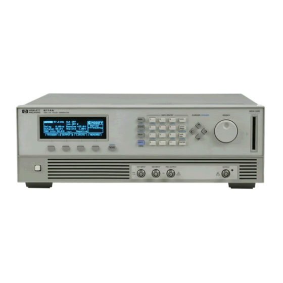
Programmable Pulse Generator 100 V/2 A
Brand:
HP
| Category:
Inverter
| Size: 6.97 MB
Table of Contents
Table of Contents
5
Replacing the Fuse
15
Power Cable
16
Rack-Mounting Accessories
17
Ventilation Requirements
17
Thermal Protection
17
Overheating Detection
17
Operating Environment
18
Installing Upgrades
19
How to Make a Firmware Update for HP 8114A
20
Supported Hardware
20
Procedure
20
Memory Sizes
22
EEPROM and RAM Sizes on the PC Boards
22
Restoring Default Settings
22
Using the HP-IB Device Command
22
Overwriting Settings
22
Firmware Upgrade Cards
23
Memory Card Sizes
23
HP 8114A Pulse Generator Specifications
25
General
25
Environmental
25
Safety
25
Power Requirements
25
Maximum Dimensions (H X W X D)
25
Weight
25
Net
25
Shipping
25
Recalibration Period
26
Warranty
26
Acoustic Noise Pressure
26
Declaration of Conformity
27
We Declare that the Product
27
Supplementary Information
27
Output
28
Amplitude
28
Range
28
Current
28
Accuracy
28
Resolution
28
Baseline
28
Variable Baseline (Option 001)
28
Polarity
29
Source Impedance
29
Load Compensation
29
Connector
29
On/Off
29
Output Protection
29
Limits
29
Pulse Performance
29
Overshoot/Preshoot/Ringing
29
Settling Time
29
Pulse Timing
30
Repeatability
30
Period
30
Range
30
Accuracy
30
Resolution
30
RMS-Jitter
30
Width
30
Duty-Cycle
31
Standard HP 8114A (Baseline = 0 V)
31
Variable Baseline Option 001
32
Delay
33
Fixed Delay
33
Variable Range
33
Accuracy
33
Resolution
33
RMS-Jitter
33
Double Pulse Delay
33
Minimum Period
33
Range
33
Trigger Output
34
Level
34
Output Impedance
34
Testing the HP 8114A
37
Introduction
37
Conventions Ijsed
37
Test Results Tables
37
Recommended Test Equipment and Accessories
38
50 0, 10 W Feedthrough Termination
39
Getting Started
39
Instrument Serial Numbers
39
The Product and Serial Number Screen with Variable
40
Test 1: Period
41
Test Specifications
41
Equipment Needed
41
Procedure
41
Test 2: Width
43
Test Specifications
43
Equipment Needed
43
Procedure
43
Test 3: Delay
46
Test Specifications
49
Procedure
49
Test 4: Double Pulse Delay
49
Equipment Needed
49
Procedure
53
Test 5: Jitter
53
Test 5.1: Period Jitter
53
Test Specifications
53
Equipment Needed
53
Test 5.2: Width Jitter
56
Test Specifications
56
Equipment Needed
56
Procedure
56
Test 5.3: Delay Jitter
59
Test Specifications
59
Equipment Needed
59
Procedure
59
Test 6: Amplitude
61
Test Specifications
61
Equipment Needed
61
Calculating out Measurement Uncertainties
61
A) Calculation for 500 into 5061 Measurements
62
Procedure
62
Equipment Set-Up 2 for Amplitude Test
63
B) Calculation for HIZ (High-Z) into 5062 Measurements
64
Procedure
64
Procedure
67
B) Amplitude Test (from HIZ {High-Z} into 500)
68
Procedure
68
Test 7: Variable Baseline (Option 001)
70
Test Specifications
70
Equipment Needed
70
Procedure
70
Test 8: Transition Time
72
Test Specifications
72
Equipment Needed
72
Test &La: Leading Edge Test
73
Procedure
73
Test &Lb: Trailing Edge Test
74
Procedure
74
Test 8.2A: Leading Edge Test
75
Procedure
75
Test 8.2B: Trailing Edge Test
76
Procedure
76
Test 9: Pulse Aberration Test
77
Equipment Needed
77
Procedure
77
Preshoot
78
HP 8114A Performance Test Records
80
Disassembly and Reassembly
91
ESD Protection
91
Terms Used and What They Mean
92
The Tools You Need
92
Inside the HP 8114A
93
Instructions for Replacing or Retrofitting HP 8114A Subassemblies
94
Removing the Instrument Cover
95
Refitting the Instrument Cover
95
Rear Panel View Showing Cover Fixing Screws
95
Removing the Power Supply
96
Rear Panel View Showing the Lever Point for the Screw
96
Power Supply and Primary Section Shielding Location
96
Refitting the Power Supply
97
Removing the Variable Baseline (if Option 001 Is Installed)
98
Refitting the Variable Baseline
98
Location of the Variable Baseline (Option 001)
98
Removing the Power Supply Fan
99
Refitting the Power Supply Fan
100
Removing the Microprocessor Board
101
Location of the Microprocessor Board
101
Top View Showing the Microprocessor Securing Screws
101
Refitting the Microprocessor Board
102
Removing the Timing Board
103
Refitting the Timing Board
103
Removing the Output Board
104
Location of the Power Load Resistor and Power FET
105
Refitting the Output Board
106
Information to the Replacement Output Board
106
Removing the Output Board Fan
107
Refitting the Output Board Fan
107
Removing the Motherboard
108
Location of the Motherboard
108
Refitting the Motherboard
109
Removing the Memory-Card Connector Board
110
Refitting the Memory-Card Connector Board
110
Location of the Memory-Card Connector Board
110
Removing the Front Panel
111
How to Remove PC Boards from Plastic Support Clips
112
Front Panel Subassemblies
112
The Front Panel Subassemblies
113
Removing the Front Panel Subassemblies
114
Replacing or Refitting the Front Panel Subassemblies
116
How to Fit PC Boards into Plastic Support Clips
116
Points to Observe When Refitting or Replacing Front Panel Subassemblies
116
Replacing or Refitting the Motherboard
117
Troubleshooting
119
Selftest
120
Power-Up Selftest
120
Extended Selftest
120
Confidence Level
120
Microprocessor Selftest Failure Messages
120
Signal Boards Selftest
121
Timing Board Selftest
121
Timing Board Selftest Failure Messages
122
Output Board Selftest
122
Output Board Selftest Failure Messages
122
Initial Tests
123
Getting Started with Troubleshooting the HP 8114A
123
Power Supply Board
124
The Power Supply Board
124
Getting Started
125
Power Supplies
126
Fixed Supplies
126
Floating Supplies
127
Microprocessor Board
128
Timing Board
130
Supply Voltages
130
Supply Voltages Testpoints on the Timing Board
130
Trigger Input
131
Period Generator
131
Check for the Supply Voltages
131
Check the Current Sources for the Period Generator
131
Delay Generator
131
Check the Current Sources for the Delay Generator
131
Width Generator
132
Check for the Supply Voltages
132
Check the Current Sources for the Width Generator
132
Edge Interface
132
Differential Signal Output
133
Inhibit Input
133
Trigger Output
133
Output Board
134
Onboard Regulators
134
Fixed Supply
134
Floating Supplies
134
Optocoupler
136
Amplifier Dacs
136
Hybrid Stage
137
Variable Floating Supply (UFLVAR)
138
Relays
138
Variable Baseline (Option 001)
139
HP 8114A Error Messages and Status Register Contents
140
Error Messages
140
Register Usage
160
Warning Messages
161
Advertisement
Advertisement
Related Products
HP 8348A
HP 8642A
HP 8671B
HP 8406A
HP 8561A
HP 8411A
HP 8672a
HP 8752c
HP 8663A
HP HP 83623L
HP Categories
Desktop
Laptop
Server
Monitor
Switch
More HP Manuals
Login
Sign In
OR
Sign in with Facebook
Sign in with Google
Upload manual
Upload from disk
Upload from URL