Sign In
Upload
Manuals
Brands
HP Manuals
All in One Printer
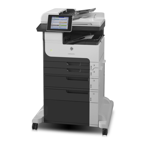
LASERJET ENTERPRISE MFP M725dn
HP LASERJET ENTERPRISE MFP M725dn Printer Manuals
Manuals and User Guides for HP LASERJET ENTERPRISE MFP M725dn Printer. We have
1
HP LASERJET ENTERPRISE MFP M725dn Printer manual available for free PDF download: Troubleshooting Manual
HP LASERJET ENTERPRISE MFP M725dn Troubleshooting Manual (546 pages)
LASERJET ENTERPRISE MFP M725
Brand:
HP
| Category:
Copier
| Size: 8.64 MB
Table of Contents
Table of Contents
7
Theory of Operation
33
Basic Operation
34
Function Structure
34
Operation Sequence
34
Figure 1-1 Function Structure
34
Figure 1-2 Engine Control System
34
Figure 1-10 Laser Scanner System
34
Table 1-1 Operation Sequence
35
Engine Control System
36
DC Controller PCA
37
Figure 1-3 DC Controller PCA
37
Figure 1-4 Motor Locations
39
Motor Control
39
Motor Locations
39
Table 1-2 Motor Locations
39
Failure Detection
40
Fan Control
41
Fan Locations
41
Figure 1-5 Fan Locations
41
Table 1-3 Fan Locations
41
Failure Detection
42
Low-Voltage Power-Supply PCA
43
Figure 1-6 Low-Voltage Power-Supply PCA
43
Over-Current/Over-Voltage/Overload Protection
44
Safety Interruption
44
Table 1-4 Low Voltage Power Supply DC Power Specifications
44
Power Supply Illumination Control
45
Power Supply Voltage Detection
45
Sleep Mode
45
High-Voltage Power-Supply PCA
46
Figure 1-7 High-Voltage Power-Supply PCA
46
Fuser Control
48
Figure 1-8 Fuser Components
48
Figure 1-9 Fuser Control System
49
Fuser Heater Protective Function
50
Fuser Temperature Control
50
Fuser Failure Detection
51
Pressure Roller Cleaning
52
Laser Scanner System
53
Laser Scanner Failure Detection
54
Laser Scanner Safety Function
54
Image-Formation System
55
Figure 1-11 Image-Formation System
55
Figure 1-12 Image-Formation Components
56
Image-Formation Process
57
Figure 1-13 Image-Formation Process
57
Latent-Image Formation Block
57
Step 1: Primary Charging
57
Step 2: Laser-Beam Exposure
58
Development Block
58
Figure 1-14 Primary Charging
58
Figure 1-15 Laser-Beam Exposure
58
Step 3: Developing
58
Transfer Block
59
Figure 1-16 Developing
59
Figure 1-17 Image Transfer
59
Step 4: Image Transfer
59
Step 5: Separation from the Drum
59
Figure 1-18 Separation from the Drum
60
Drum-Cleaning Block
61
Step 7: Drum Cleaning
61
Fuser Block
61
Step 6: Fusing
61
Toner Cartridge
61
Figure 1-19 Fusing
61
Figure 1-20 Drum Cleaning
61
Figure 1-21 Toner Cartridge Components
62
Other Image-Formation Functions
63
Drum Discharge
63
Transfer Roller Cleaning
63
Figure 1-22 Drum Discharge
63
Environment Change Control
64
Figure 1-23 Transfer Roller Cleaning
64
Pickup, Feed, and Delivery System
65
Figure 1-24 Pickup, Feed, and Delivery System
65
Figure 1-25 Pickup, Feed, and Delivery System Sensors and Switches
66
Table 1-5 Pickup, Feed, and Delivery System Sensors and Switches
66
Figure 1-26 Pickup, Feed, and Delivery-System Solenoid and Motors
68
Table 1-6 Pickup, Feed, and Delivery System Solenoid and Motors
68
Pickup-And-Feed Block
69
Figure 1-27 Pickup-And-Feed Block
69
Cassette Media-Size Detection and Cassette-Presence Detection
70
Cassette Pickup
70
Figure 1-28 Cassette Pickup Mechanism
70
Cassette Lift Operation
71
Lift-Down Operation
71
Lift-Up Operation
71
Table 1-7 Media Switch Combinations
71
Cassette Media-Presence Detection
72
Cassette Multiple-Feed Prevention
72
Figure 1-29 Cassette Lift Operation
72
Figure 1-30 Cassette Multiple-Feed Prevention
73
Figure 1-31 MP Tray Pickup
74
MP Tray Media-Presence Detection
74
MP Tray Pickup
74
Feed-Speed Control
75
Figure 1-32 MP Tray Multiple-Feed Prevention
75
MP Tray Multiple-Feed Prevention
75
Figure 1-33 Skew-Feed Prevention
77
Skew-Feed Prevention
77
Media-Length Detection
78
Fuse and Delivery Block
79
Figure 1-34 Fuse and Delivery Block
79
Figure 1-35 Loop Control
80
Loop Control
80
Figure 1-36 Output bin Media-Full Detection
81
Output bin Media-Full Detection
81
Jam Detection
82
Figure 1-37 Product Engine Jam Detection Sensors and Switches
83
No Pick Jam 1
83
Feed Stay Jam 1
84
Fuser Output Delay Jam 1
84
Fuser Output Stay Jam 1
84
Output Delay Jam 1
84
Output Delay Jam 2
84
Output Stay Jam 1
84
Automatic Delivery
85
Door Open Jam 1
85
Fuser Wrap Jam 1
85
Multiple-Feed Jam 1
85
Residual Paper Jam 1
85
Scanning/Image Capture System
86
Automatic Document Feed System
86
Scanner
86
Sensors in the Document Feeder
86
Document Feeder Paper Path
87
Figure 1-38 Document Feeder Path for Single-Sided Documents
87
Figure 1-39 Document Feeder Path for Two-Sided Documents
88
500-Sheet Paper Feeder (Tray 4)
89
Figure 1-40 500-Sheet Paper Feeder Paper Path
89
500-Sheet Paper Feeder Motor Control
90
Figure 1-41 500-Sheet Paper Feeder Signal Flow
90
Figure 1-42 500-Sheet Paper Feeder Motor Locations
90
Table 1-8 500-Sheet Paper Feeder Electrical Components
90
500-Sheet Paper Feeder Failure Detection
91
500-Sheet Paper Feeder Pickup and Feed Operation
91
Figure 1-43 500-Sheet Paper Feeder Pickup and Feed Components
91
Table 1-10 500-Sheet Paper Feeder Pickup and Feed Components
91
Table 1-9 500-Sheet Paper Feeder Motors
91
500-Sheet Paper Feeder Cassette Media-Size Detection and Cassette-Presence Detection
92
500-Sheet Paper Feeder Cassette Pickup
92
Figure 1-44 500-Sheet Paper Feeder Pickup and Feed Cassette Pickup
92
500-Sheet Paper Feeder Lift-Up Operation
93
Figure 1-45 500-Sheet Paper Feeder Lift-Up Operation
93
Table 1-11 500-Sheet Paper Feeder Media Switch Combinations
93
500-Sheet Paper Feeder Cassette Media-Presence Detection
94
500-Sheet Paper Feeder Cassette Multiple-Feed Prevention
94
500-Sheet Paper Feeder Jam Detection
95
Figure 1-46 500-Sheet Paper Feeder Multiple-Feed Prevention
95
Figure 1-47 500-Sheet Paper Feeder Cassette Jam Detection Sensor
95
No Pick Jam 2
95
Residual Paper Jam 1
95
500-Sheet Paper Feeder Automatic Delivery
96
Door Open Jam 1
96
1X500 and 3X500 Paper Feeder and Stand
97
Figure 1-48 Paper Deck Paper Path
98
Figure 1-49 Paper Deck Signal Flow
99
Table 1-12 Paper Deck Electrical Components
99
Figure 1-50 Paper Deck Motors
101
Paper Deck Failure Detection
101
Paper Deck Motor Control
101
Paper Deck Pickup-And-Feed Operation
101
Table 1-13 Paper Deck Motors
101
Figure 1-51 Paper Deck Pickup-And-Feed Components
102
Table 1-14 Paper Deck Pickup-And-Feed Operation Components
102
Paper Deck Cassette Media-Size Detection and Cassette-Presence Detection
103
Table 1-15 Paper Deck Media Switch Combinations
103
Figure 1-52 Paper Deck Lift-Up Operation
104
Paper Deck Lift-Up Operation
104
Figure 1-53 Paper Deck Jam Detection Sensors
105
No Pick Jam 2
105
Paper Deck Cassette Media-Presence Detection
105
Paper Deck Jam Detection
105
Door Open Jam 1
106
No Pick Jam 3 (3X500-Sheet Paper Deck Only)
106
Paper Deck Automatic Delivery
106
Residual Paper Jam 1
106
3,500-Sheet High-Capacity Input (HCI) Feeder
107
Figure 1-54 HCI Paper Path
107
Figure 1-55 HCI Signal Flow
108
Table 1-16 HCI Electrical Components
108
Figure 1-56 HCI Motors
109
HCI Failure Detection
109
HCI Motor Control
109
Table 1-17 HCI Motors
109
Figure 1-57 HCI Pickup-And-Feed Operation
110
HCI Pickup-And-Feed Operation
110
Table 1-18 HCI Pickup-And-Feed Operation Components
110
HCI Cassette Media-Size Detection and Cassette-Presence Detection
111
Figure 1-58 HCI Lift-Up Operation
112
HCI Lift-Up Operation
112
HCI Cassette Media-Presence Detection
113
HCI Jam Detection
114
Figure 1-59 HCI Jam Detection Sensors
114
No Pick Jam 2
114
No Pick Jam 3
114
Door Open Jam 1
115
Residual Paper Jam 1
115
HCI Automatic Delivery
115
Duplexer
116
Figure 1-60 Duplexer Paper Path
116
Figure 1-61 Duplexer Signal Flow
117
Table 1-19 Duplexer Electrical Components
117
Duplexer Motor Control
118
Duplexer Motor Failure Detection
118
Figure 1-62 Duplexer Motor
118
Table 1-20 Duplexer Motor
118
Duplexer Fan Control
119
Duplexer Fan Failure Detection
119
Figure 1-63 Duplexer Fan
119
Table 1-21 Duplexer Fan
119
Duplexer Reverse-And-Feed Operation
120
Figure 1-64 Duplexer Reverse-And-Feed Operation
120
Table 1-22 Duplexer Reverse-And-Feed Components
120
Duplexer Reverse-And Feed-Operation Sequence
121
Side Misregistration Detection
121
Figure 1-65 Duplexer Side Misregistration Detection
122
Side Misregistration Failure Detection
123
Duplexer Jam Detection
124
Figure 1-66 Duplexer Jam Detection Sensors
124
Duplex Re-Pickup Jam 1
125
Duplex Re-Pickup Jam 2
125
Duplex Re-Pickup Jam 3
125
Fuser Output Stay Jam 2
125
Residual Paper Jam 1
125
Reverse Jam 1
125
Duplexer Automatic Delivery
125
Stapler/Stacker
126
Figure 1-67 Stapler/Stacker Paper Path
126
Figure 1-68 Stapler/Stacker Signal Flow
127
Stapler/Stacker Motor Control
128
Figure 1-69 Stapler/Stacker Motor Locations
128
Stapler/Stacker Failure Detection
129
Stapler/Stacker Feed and Delivery Operation
130
Figure 1-70 Stapler/Stacker Feed and Delivery Operation
130
Figure 1-71 Staple Mode Mode Begins
132
Staple Mode/Stack Align Mode
132
Figure 1-72 Jogger Guide in the Waiting Position
133
Figure 1-73 Alignment-Alienation Motor Separates Output Rollers
134
Figure 1-74 Jogger Guide in the Alignment Position
135
Figure 1-75 Leading End Alienation Roller Activates
135
Figure 1-76 Alignment Complete
136
Figure 1-77 Jogger Guide in the Turnout Position
137
Figure 1-78 Paper Stack Goes to the Output bin
137
Figure 1-79 Paper Stack Goes to the Output bin in Stacker Mode
138
Stacker Mode
138
Stapler/Stacker Jam Detection
139
Figure 1-80 Stapler/Stacker Jam Sensors
139
Inlet Delay Jam
139
Inlet Stay Jam
139
Paper Stack Output Stay Jam
139
Residual Paper Jam
140
Stapler/Stacker Automatic Delivery
140
Figure 1-81 Stapler Components
141
Stapler
141
Solve Problems
143
Solve Problems Checklist
144
Helpful Printed Pages
146
Menu Map
146
Current Settings Pages
146
Preboot Menu Options
147
Table 2-1 Preboot Menu Options (1 of 6)
147
Table 2-2 Preboot Menu Options (2 of 6)
149
Table 2-3 Preboot Menu Options (3 of 6)
150
Table 2-4 Preboot Menu Options (4 of 6)
151
Table 2-5 Preboot Menu Options (5 of 6)
151
Table 2-6 Preboot Menu Options (6 of 6)
152
Troubleshooting Process
154
Determine the Problem Source
154
Table 2-7 Troubleshooting Flowchart
154
Troubleshooting Flowchart
154
Power Subsystem
155
Power-On Checks
155
Power-On Troubleshooting Overview
155
Control-Panel Checks
156
Control-Panel Diagnostic Flowcharts
158
Figure 2-1 Touchscreen Blank, White, or DIM (no Image)
159
Touchscreen Black, White, or DIM (no Image)
159
Figure 2-2 Touchscreen Is Slow to Respond or Requires Multiple Presses to Respond
160
Respond
160
Touchscreen Is Slow to Respond or Requires Multiple Presses to
160
Figure 2-3 Touchscreen Has an Unresponsive Zone
161
Touchscreen Has an Unresponsive Zone
161
Figure 2-4 no Control-Panel Sound
162
No Control-Panel Sound
162
Home Button Is Unresponsive
163
Hardware Integration Pocket (HIP) Is Not Functioning (Control Panel Functional)
164
Scanning Subsystem
164
Figure 2-6 Hardware Integration Pocket (HIP) Is Not Functioning (Control Panel Functional)
164
Tools for Troubleshooting
165
Individual Component Diagnostics
165
LED Status
165
Understand Lights on the Formatter
165
Table 2-8 Heartbeat LED, Status
166
Engine Diagnostics
167
Engine-Test Button
167
Figure 2-7 Locating the Engine-Test
168
Paper Path Test
170
Paper Path Sensor Tests
171
Table 2-9 Paper-Path Sensors
171
Manual Sensor Tests
172
Table 2-10 Manual Sensor Tests
172
Cartridge Door Switch (SW3)
174
Figure 2-8 Test the Cartridge Door Switch
174
Figure 2-9 Test the Left Door Switch
175
Left Door Switch (SW1)
175
Right Door Sensor (SR8)
176
Cartridge Install Sensor (SR1)
177
Figure 2-10 Test the Top Sensor
178
TOP (Top-Of-Page) Sensor (SR9)
178
Figure 2-11 Fuser Loop Sensor
179
Fuser Loop Sensor (SR6)
179
Figure 2-12 Fuser Output Sensor
180
Fuser Output Sensor (SR12)
180
Duplex Switchback Sensor (SR1)
181
Figure 2-13 Duplex Switchback Sensor
181
Duplexer Refeed Sensor (SR2)
182
Figure 2-14 Duplexer Refeed Sensor
182
Tray 4 Feed Sensor (SR1)
183
Figure 2-15 Tray 4 Feed Sensor
183
Output Sensor (SR3)
184
Figure 2-16 Output Sensor
184
Tray/Bin Manual Sensor Tests
185
Table 2-11 Tray/Bin Manual Sensor Test
185
Base Product Trays
187
Figure 2-17 Tray 1 Paper Sensor
187
Figure 2-18 Tray 2 Paper Sensor
188
Figure 2-19 Tray 2 Paper Surface Sensor
189
Figure 2-20 Tray 2 Paper Size Switches
190
Figure 2-21 Tray 3 Paper Sensor
191
Figure 2-22 Tray 3 Paper Surface Sensor
192
Figure 2-23 Tray 3 Paper Size Switches
193
Figure 2-24 Output bin Full Sensor
194
Figure 2-25 Tray 4 Paper Sensor
195
Optional 500-Sheet Paper Tray (Tray 4)
195
Figure 2-26 Tray 4 Paper Surface Sensor
196
Figure 2-27 Tray 4 Paper Size Switches
197
Figure 2-28 Tray 4 Feed Sensor
198
Figure 2-29 Lower Right Door Sensor
199
1X500 and 3X500 Paper Deck Trays
200
Figure 2-30 Test the Tray 4 Door Switch
201
Figure 2-31 Tray 4 Paper Sensor
204
HCI Trays
204
Figure 2-32 Tray 4 Paper Surface Sensor
205
Figure 2-33 Tray 4 Paper Size Sensor
206
Figure 2-34 Tray 4 Paper Feed Sensor
207
Figure 2-35 Tray 4 Door Open Sensor
208
Figure 2-36 Tray 5 Paper Sensor
209
Figure 2-37 Tray Paper Surface Sensor
210
Figure 2-38 Tray 5 Paper Size Sensor
211
Figure 2-39 Tray 5 Feed Sensor
212
Scanner Sensor Tests
213
Figure 2-40 HCI Exit Sensor
213
Print/Stop Test
215
Component Tests
216
Control-Panel Tests
216
Half Self-Test
216
Drum Rotation Test Check
217
Component Test (Special-Mode Test)
217
Table 2-12 Component Tests
217
Diagrams
219
Block Diagrams
219
Figure 2-41 Product Cross Section
219
Figure 2-42 Optional Paper Feeder (Tray 3 and Tray 4) Cross Section
220
Table 2-13 1X500-Sheet Paper Deck Cross Section
221
Figure 2-43 1X500-Sheet Paper Deck Cross Section
221
Table 2-14 3X500-Sheet Paper Deck Cross Section
222
Figure 2-44 3X500-Sheet Paper Deck Cross Section
222
Table 2-15 3,500-Sheet HCI Cross Section
223
Figure 2-45 3,500-Sheet HCI Cross Section
223
Location of Connectors
224
DC Controller Connections
224
Figure 2-46 DC Controller Connections
224
Plug/Jack Locations
225
Locations of Major Components
226
Figure 2-47 Base Product External Components
226
Figure 2-48 1X500-Sheet Paper Feeder External Components
227
Figure 2-49 1X500-Sheet Paper Deck External Components
228
Figure 2-50 3X500-Sheet Paper Deck External Components
229
Figure 2-51 3500-Sheet Paper Deck (HCI) External Components
230
Figure 2-52 Duplexer External Components
231
Figure 2-53 Stapler/Stacker External Components
232
Figure 2-54 Major Component Locations (1 of 3)
233
Figure 2-55 Major Component Locations (2 of 3)
234
Figure 2-56 Major Component Locations (3 of 3)
234
Figure 2-57 PCA Component Locations
235
Figure 2-58 Motor Locations
235
Figure 2-59 Fan Locations
236
Figure 2-60 Roller Locations
236
Figure 2-61 Sensor Locations (Base Product)
237
Figure 2-62 Switch Locations (Base Product)
238
Figure 2-63 Solenoid Location (Base Product)
239
Figure 2-64 Clutch Location (Base Product)
239
Figure 2-65 1X500 Paper Feeder Internal Component Locations
240
Figure 2-66 1X500 Paper Deck Internal Component Locations
241
Figure 2-67 3X500 Paper Deck Internal Component Locations
242
Figure 2-68 3500-Sheet Paper Deck (HCI) Internal Component Locations (1 of 2)
243
Figure 2-69 3500-Sheet Paper Deck (HCI) Internal Component Locations (2 of 2)
244
Figure 2-70 Stapler/Stacker Internal Component Locations
245
General Timing Charts
246
Figure 2-71 General Timing Chart
246
Circuit Diagrams
247
Figure 2-72 General Circuit Diagram (1 of 2)
247
Figure 2-73 General Circuit Diagram (2 of 2)
248
Internal Print-Quality Test Pages
249
Clean the Paper Path
249
Set up an Auto Cleaning Page
249
Print a Configuration Page
250
Configuration Page
250
Figure 2-74 Configuration Page
250
Figure 2-75 HP Embedded Jetdirect Page
251
HP Embedded Jetdirect Page
251
Finding Important Information on the Configuration Pages
252
Table 2-16 Important Information on the Configuration
252
Control Panel Menus
253
Administration Menu
253
Reports Menu
253
General Settings Menu
255
Copy Settings Menu
263
Scan/Digital Send Settings Menu
270
Fax Settings Menu
282
General Print Settings Menu
295
Default Print Options Menu
298
Display Settings Menu
300
Manage Supplies Menu
302
Manage Trays Menu
305
Network Settings Menu
307
Troubleshooting Menu
321
Backup/Restore Menu
325
Device Maintenance Menu
325
Calibration/Cleaning Menu
326
Service Menu
327
USB Firmware Upgrade Menu
327
A1 Jam in Upper Left Door
328
Control-Panel Message Types
328
Control-Panel Messages
328
Interpret Control-Panel Messages
328
YY Internal Clock Error to Continue, Touch "OK
328
A1 Jam in Upper bin
329
D1 Jam in Upper Left Door
329
FF Jam in Upper bin
329
FF Jam in Upper Left Door
329
A4.D4 Jam in Lower Right Door
330
Jam in Stapler
330
A4.D4 Jam in Tray 4
331
A4.D5 Jam in Lower Right Door
331
A4.D5 Jam in Middle Right Door
332
A4.D6 Jam in Lower Right Door
333
A4.D6 Jam in Middle Right Door
333
A4.FF Jam in Tray 4 or 13.A4.FF Jam in Lower Right Door or 13.A4.FF Jam in Middle Right Door
334
A5.D5 Jam in Tray 5
334
A5.D6 Jam in Lower Right Door
335
A5.FF Jam in Tray 5 or 13.A5.FF Jam in Lower Right Door or 13.A5.FF Jam Tray 4 (Inner Flap)
335
A6.D6 Jam in Tray 6
336
A6.FF Jam in Tray 6 or 13.A6.FF Jam Tray 5 (Inner Flap)
336
A7.D5 Jam in Lower Right Door
337
A7.D5 Jam Tray 4 (Inner Flap)
337
A7.D6 Jam Tray 5 (Inner Flap)
338
A7.FF Jam in Tray 4 or 13.A7.FF Jam in Tray 5 or 13.A7.FF Jam in Lower Right Door
338
AA.EE Door Open Jam
338
AB.EE Door Open Jam
339
AC.EE Door Open Jam
339
AD.EE Door Open Jam
340
B2.AD Jam in Top Cover Area
340
B2.AX Jam in Top Cover Area
341
B2.D1 Jam in Tray 1
342
B2.D2 Jam in Top Cover Area (Tray 2)
342
B2.D3 Jam in Top Cover Area (Tray 3) (no Optional Input Devices Installed)
343
B2.D3 Jam in Top Cover Area (Tray 3) (Optional Input Devices Installed)
344
B2.DD Jam in Top Cover Area
344
B2.DX Jam in Top Cover Area
345
B2.FF Jam in Top Cover Area
346
B4.FF Jam in Top Cover Area
346
B9.AX Fuser Area Jam
347
B9.CX Fuser Wrap Jam
347
B9.DD Fuser Area Jam (Top Cover)
348
B9.FF Jam in Left Door
349
BA.EE Door Open Jam
349
D1.DX Jam in Left Door
349
D1.FF Jam in Left Door
350
D3.00 Jam in Top Cover Area
350
D3.DX Jam in Duplexer
351
D3.FF Jam in Top Cover Area
351
DE.EE Jam in Duplexer (During a Print Job)
352
E1.DX Jam in Left Door
352
E1.FF Jam in Left Door
353
E6.AX Jam in Left Door
353
E6.BD Jam in Left Door
354
E6.BX Jam in Left Door
354
E6.DX Jam in Left Door
354
E6.Ff
355
EA.EE Door Open Jam
355
Ff.ff
356
WX.YZ Fuser Area Jam (Top Cover)
356
Insufficient Memory: <Device> to Continue, Touch "OK
357
Page too Complex to Continue, Touch "OK
357
C.XX
366
WX.YZ Used Board/Disk Installed
373
EIO <X> Buffer Overflow to Continue, Touch "OK
374
YZ Unexpected Size in Tray <X
375
Options
375
YZ Unexpected Type in Tray <X
376
YZ Unexpected Type in Tray <X> to Use Another Tray, Touch "Options
377
WX.YZ Error to Use Another Tray, Touch "Options
378
347
379
348
380
349
381
XX.YY Error to Continue Turn off then on
381
WX.YZ Fuser Error to Continue Turn off then on
382
YY Error to Continue Turn off then on
385
Error to Continue Turn off then on
386
XX>.00 Error to Continue Turn off then on
386
XX.YY Error
387
XX.YY DC Controller Error to Continue Turn off then on
387
YY Error to Continue Turn off then on
388
Error
388
Environmental Sensor Malfunction
388
Error to Continue Turn off then on
389
Error to Continue Turn off then on
390
Tray <Y> Lifting Error
391
Media Input Source <Y> Pickup Mechanism Malfunction
392
No System to Continue Turn off then on
393
Output Accessory Failure to Continue Turn off then on
393
Output Accessory Failure to Continue Turn off then on
394
YY Error to Continue, Touch "OK
394
Error to Continue Turn off then on
394
X.YY Embedded Jetdirect Error
395
WX.00 Wireless Network Error to Continue Turn off then on
396
WX.YZ Embedded Jetdirect Error to Continue Turn off then on
397
YY.YY EIO Error to Continue Turn off then on
397
Corrupt Data in X Volume
398
Upgrade Not Performed File Is Corrupt
398
Upgrade Not Performed Timeout During Receive
398
Upgrade Not Performed Error Writing to Disk
399
Upgrade Not Performed Timeout During Receive
399
Upgrade Not Performed Error Reading Upgrade
399
Upgrade Not Performed Error Reading Upgrade
400
Upgrade Canceled by User
400
Upgrade Not Performed the File Is Invalid
401
369
401
370
402
Unsupported Disk
403
Unknown Disk
403
Incorrect Disk
404
Disk Malfunction
404
Disk Data Error
404
No Disk Installed
404
Disk Is Not Bootable Please Download Firmware
404
XX.yy
405
Binname> Full Remove All Paper from bin
405
Bad Optional Tray Connection
405
Black Cartridge Low
406
Black Cartridge very Low
406
Black Cartridge very Low to Continue, Touch "OK
406
Card Slot Device Failure to Clear Touch "Clear
406
Card Slot File Operation Failed to Clear Touch "Clear
407
Card Slot File System Is Full to Clear Touch "Clear
407
Card Slot Is Write Protected to Clear Touch "Clear
407
Card Slot Not Initialized to Clear Touch "Clear
407
Cartridge Ship Mode
407
Chosen Personality Not Available to Continue, Touch "OK
407
Cleaning Disk <X>% Complete Do Not Power off
408
Close Left Door
408
Close Right Door
408
Close Top Cover
408
Data Received
409
Disk Full Delete Stored Jobs
409
Disk Low Delete Stored Jobs
409
EIO <X> Disk Not Functional
409
EIO <X> Disk Spinning up
410
EIO Device Failure to Clear Touch "Clear
410
EIO File Operation Failed to Clear Touch "Clear
410
EIO File System Is Full to Clear Touch "Clear
410
EIO Is Write Protected to Clear Touch "Clear
411
EIO Not Initialized to Clear Touch "Clear
411
Event Log Is Empty
411
Fuser Kit Low
411
Fuser Kit very Low
411
Fuser Kit very Low to Continue, Touch "OK
412
Incompatible <Supply
412
Incompatible Supplies
412
Initializing
412
Install Black Cartridge
413
Install Fuser Unit
413
Install Supplies
413
Internal Disk Device Failure to Clear Touch "Clear
413
Internal Disk File Operation Failed to Clear Touch "Clear
414
Internal Disk File System Is Full to Clear Touch "Clear
414
Internal Disk Is Write Protected to Clear Touch "Clear
414
Internal Disk Not Found
414
Internal Disk Not Functional
414
Internal Disk Not Initialized to Clear Touch "Clear
414
Internal Disk Spinning up
415
Load Tray 1 [Type] [Size]
415
Load Tray 1 [Type] [Size] to Continue, Touch "OK
415
Load Tray <X>: [Size]
415
Load Tray <X>: [Size] to Continue, Touch "OK
416
Load Tray <X>: [Size] to Use Another Tray, Touch "Options
416
Load Tray <X>: [Type], [Size]
416
Load Tray <X>: [Type], [Size] to Use Another Tray, Touch "Options
417
Manually Feed Output Stack then Touch "OK" to Print Second Sides
417
Manually Feed: [Size]
418
Manually Feed: [Size] to Continue, Touch "OK
418
Manually Feed: [Size] to Use Another Tray, Touch "Options
418
Manually Feed: [Type], [Size] to Continue, Touch "OK
419
Manually Feed: [Type], [Size] to Use Another Tray, Touch "Options
419
Moving Solenoid
419
Moving Solenoid and Motor
419
No Job to Cancel
419
Output bin Full
420
Paperless Mode
420
Printing Engine Test
420
Printing Stopped to Continue, Touch "OK
420
RAM Disk Device Failure to Clear Touch "Clear
421
RAM Disk File Operation Failed to Clear Touch "Clear
421
RAM Disk File System Is Full to Clear Touch "Clear
421
RAM Disk Is Write Protected to Clear Touch "Clear
421
RAM Disk Not Initialized to Clear Touch "Clear
421
Remove Cartridge Lock
421
Remove the Toner Cartridge
422
Replace Black Cartridge
422
Replace Fuser Kit
422
Replace Supplies
423
ROM Disk Device Failed to Clear Touch "Clear
423
ROM Disk File Operation Failed to Clear Touch "Clear
423
ROM Disk File System Is Full to Clear Touch "Clear
423
ROM Disk Is Write Protected to Clear Touch "Clear
424
ROM Disk Not Initialized to Clear Touch "Clear
424
Size Mismatch in Tray <X
424
Standard bin Full Remove All Paper from bin
424
Supplies Low
425
Supplies very Low to Continue, Touch "OK
425
Supply Memory Warning
425
Tray <X> Empty: [Size]
425
Tray <X> Empty: [Type], [Size]
426
Tray <X> Open
426
Tray <X> Overfilled Remove Excess Paper
426
Tray <X> Overfilled to Use Another Tray, Touch "Options
426
Type Mismatch Tray <X
427
Unable to Cancel Firmware Update Job
427
Unable to Install the Firmware
427
Unsupported Drive Installed
428
Unsupported Supply in Use
428
Unsupported Supply Installed
428
Unsupported Supply Installed to Continue, Touch "OK
428
Unsupported Tray Configuration
428
Unsupported USB Accessory Detected Remove USB Accessory
429
Upgrade Complete to Continue Turn off then on
429
USB Accessory Needs too Much Power Remove USB and Turn off then on
429
USB Accessory Not Functional
429
Properly
429
USB Is Write Protected to Clear Touch "Clear
430
USB Not Initialized to Clear Touch "Clear
430
USB Storage Accessory Removed Clearing any Associated Data
430
USB Storage Device Failure to Clear Touch "Clear
430
USB Storage File Operation Failed to Clear Touch "Clear
430
USB Storage File System Is Full to Clear Touch "Clear
431
Used Supply in Use
431
Used Supply Installed to Continue, Touch "OK
431
Event Log Messages
432
Figure 2-76 Sample Event Log
432
Clear an Event Log
433
Event Log Message Table
433
Print or View an Event Log
433
Clear Jams
436
Jam Locations
436
Figure 2-77 Product Base Paper Path and Sensor Locations (1 of 2)
437
Figure 2-78 Product Base Paper Path and Sensor Locations (2 of 2)
437
Figure 2-79 1X500 Paper Feeder Paper Path and Sensor Locations
437
Figure 2-80 1X500 and 3X500 Paper Deck Paper Path and Sensor Locations
438
Figure 2-81 High Capacity Input (HCI) Paper Path and Sensor Locations
438
Auto-Navigation for Clearing Jams
439
Clear Jams in the Document Feeder
439
Figure 2-82 Stapler/Stacker Paper Path and Sensor Locations
439
Clear Jams in the Output-Bin Area
441
Clear Jams in the Stapler/Stacker
441
Clear Staple Jams
443
Clear Jams in Tray 1
446
Clear Jams in Tray 2 or Tray 3
447
Clear Jams in the 500-Sheet Trays
449
Clear Jams in the 3,500-Sheet High-Capacity Tray
450
Clear Jams from the Toner-Cartridge Area
453
Clear Jams in the Fuser
456
Clear Jams from the Duplexer
458
Solve Paper-Handling Problems
459
The Product Does Not Pick up Paper
459
The Product Picks up Multiple Sheets of Paper
459
The Document Feeder Jams, Skews, or Picks up Multiple Sheets of Paper
460
Use Manual Print Modes
461
Table 2-32 Print Modes under the Adjust Paper Types Sub Menu
461
Table 2-33 MP Modes under the Optimize Submenu
462
Print Quality Troubleshooting Tools
463
Repetitive Defects Measurements
463
Solve Image-Quality Problems
464
Image Defect Examples
464
Table 2-34 Image Defect Examples
464
Clean the Product
472
Check the Scanner Glass for Dirt or Smudges
472
Print a Cleaning Page
472
Clean the Pickup Rollers and Separation Pad in the Document Feeder
474
Solve Performance Problems
477
Table 2-35 Solve Performance Problems
477
Solve Connectivity Problems
478
Solve USB Connection Problems
478
Solve Wired Network Problems
478
The Computer Is Using the Incorrect IP Address for the Product
478
The Product Has a Poor Physical Connection
478
New Software Programs Might be Causing Compatibility Problems
479
The Computer Is Unable to Communicate with the Product
479
The Computer or Workstation Might be Set up Incorrectly
479
The Product Is Disabled, or Other Network Settings Are Incorrect
479
The Product Is Using Incorrect Link and Duplex Settings for the Network
479
Service Mode Functions
480
Service Menu
480
Convert Service ID to Actual Date
483
Product Resets
483
Restore Factory-Set Defaults
483
Restore the Service ID
483
Active and Repository Firmware Locations
484
Cold Reset Using Preboot Menu
484
Format Disk and Partial Clean Functions
484
Product Cold Reset
484
Execute a 3 Partial Clean
485
Partial Clean
485
Execute a 2 Format Disk
486
Format Disk
486
Solve Fax Problems
487
Are You Using a Surge-Protection Device
487
Checklist for Solving Fax Problems
487
What Type of Phone Line Are You Using
487
Are You Using a Phone Company Voice-Messaging Service or an Answering Machine
488
Does Your Phone Line Have a Call-Waiting Feature
488
Check Fax Accessory Status
489
General Fax Problems
490
Use Fax over Voip Networks
491
Problems with Receiving Faxes
492
Problems with Sending Faxes
494
Fax Error Codes
496
Fax Error Messages on the Product Control Panel
496
Send-Fax Messages
497
Table 2-36 Send-Fax Messages
497
Receive-Fax Messages
498
Table 2-37 Receive-Fax Messages
498
Service Settings
499
Settings in the Troubleshooting Menu
499
Product Upgrades
500
Determine the Installed Revision of Firmware
500
Embedded Web Server
500
Perform a Firmware Upgrade
500
USB Storage Device (Preboot Menu)
501
USB Storage Device (Control-Panel Menu)
502
Appendix A Service and Support
503
Hewlett-Packard Limited Warranty Statement
504
Hp's Premium Protection Warranty: Laserjet Toner Cartridge Limited Warranty Statement
506
HP Policy on Non-HP Supplies
507
HP Anticounterfeit Web Site
508
Data Stored on the Toner Cartridge
509
End User License Agreement
510
Openssl
513
Customer Self-Repair Warranty Service
514
Customer Support
515
Appendix B Product Specifications
517
Physical Specifications
518
Power Consumption, Electrical Specifications, and Acoustic Emissions
518
Environmental Specifications
518
Table B-1 Product Dimensions and Weights
518
Table B-2 Product Dimensions with All Doors and Trays Fully Opened
518
Table B-3 Operating-Environment Specifications
518
Appendix C Regulatory Information
519
FCC Regulations
520
Environmental Product Stewardship Program
521
Protecting the Environment
521
Ozone Production
521
Power Consumption
521
Toner Consumption
521
Paper Use
521
Plastics
521
HP Laserjet Print Supplies
522
Return and Recycling Instructions
522
Multiple Returns (more than One Cartridge)
522
Shipping
522
Single Returns
522
United States and Puerto Rico
522
Non-U.S. Returns
523
Paper
523
Material Restrictions
523
Disposal of Waste Equipment by Users
524
Electronic Hardware Recycling
524
Chemical Substances
524
Material Safety Data Sheet (MSDS)
524
For more Information
524
Declaration of Conformity
526
Declaration of Conformity (Fax Models)
528
Certificate of Volatility
530
Figure C-1 Certificate of Volatility (1 of 2)
530
Figure C-2 Certificate of Volatility (2 of 2)
531
Safety Statements
532
Laser Safety
532
Canadian DOC Regulations
532
VCCI Statement (Japan)
532
Power Cord Instructions
532
Power Cord Statement (Japan)
532
EMC Statement (China)
533
EMC Statement (Korea)
533
EMI Statement (Taiwan)
533
Laser Statement for Finland
533
GS Statement (Germany)
535
Substances Table (China)
535
Restriction on Hazardous Substances Statement (Turkey)
535
Restriction on Hazardous Substances Statement (Ukraine)
535
Additional Statements for Telecom (Fax) Products
536
EU Statement for Telecom Operation
536
New Zealand Telecom Statements
536
Additional FCC Statement for Telecom Products (US)
536
Telephone Consumer Protection Act (US)
537
Industry Canada CS-03 Requirements
537
Vietnam Telecom Wired/Wireless Marking for ICTQC Type Approved Products
538
Japan Telecom Mark
538
Index
539
Advertisement
Advertisement
Related Products
HP LASERJET ENTERPRISE MFP M725z
HP LASERJET ENTERPRISE MFP M725f
HP LASERJET PRO 300 Color MFP M375
HP LASERJET PRO 400 Color MFP M475
HP PageWide Managed Color MFP E77660
HP PageWide Managed Color MFP E77650
HP PageWide Managed Color MFP P77940
HP PageWide Managed Color MFP P77950
HP LaserJet M602
HP LaserJet M603
HP Categories
Desktop
Laptop
Server
Monitor
Switch
More HP Manuals
Login
Sign In
OR
Sign in with Facebook
Sign in with Google
Upload manual
Upload from disk
Upload from URL