Sign In
Upload
Manuals
Brands
HP Manuals
Laptop
nx9000 - Notebook PC
HP nx9000 - Notebook PC Business Manuals
Manuals and User Guides for HP nx9000 - Notebook PC Business. We have
6
HP nx9000 - Notebook PC Business manuals available for free PDF download: Service Manual, Limited Warranty, Accessory Manual, Product Support Bulletin
HP nx9000 - Notebook PC Service Manual (188 pages)
Notebook PC
Brand:
HP
| Category:
Laptop
| Size: 11.78 MB
Table of Contents
Table of Contents
3
Table 1-1. Notebook Products
7
Table 1-2. Product Comparisons
49
Features
54
Figure 1-1. Front View
54
Figure 1-2. Back View
55
Figure 1-3. Bottom View
56
Figure 1-4. Front View
57
Figure 1-5. Back View
58
Figure 1-6. Bottom View
59
Operation
60
Table 1-3. Activating Power Modes
60
Table 1-4. Main Status Lights (Front of Notebook)
61
Table 1-5. Keyboard Status Lights
61
Table 1-6. Fn Hot Keys
62
Figure 1-7. Resetting the Notebook
63
Specifications
64
Table 1-7. Specifications
64
Table 1-8. Accessories
68
Figure 1-8. Replaceable Module Diagram
70
Internal Design
70
Table 1-9. Functional Structure Description
71
Removal and Replacement
72
Table 2-1. Removal Cross-Reference
72
Table 2-2. Required Equipment
73
Table 2-3. Recommended Screw Torque Values
73
Disassembly Flowchart
74
Figure 2-1. Disassembly Flow
74
Figure 2-2. Removing the Battery
75
Removing the Battery
75
Figure 2-3. Removing an SDRAM Module
76
Removing a SDRAM Module
76
Figure 2-4. Removing an SDRAM Module
77
Figure 2-5. Removing the Mini-PCI Card
78
Removing the Wireless LAN Mini-PCI Card
78
Figure 2-6. Removing the Mini-PCI Card
79
Figure 2-7. Removing the Hard Disk Drive
80
Removing the Hard Disk Drive
80
Figure 2-8. Removing the Hard Disk Drive Tray
81
Replacing Small Parts
82
Table 2-4. Replacing Small Parts
82
Removing the Keyboard Cover
83
Figure 2-9. Removing the Keyboard Cover
84
Figure 2-10. Disconnecting the Speaker Cable
85
Figure 2-11. Removing the Speaker Assembly
86
Removing the Speaker Assembly
86
Removing the Keyboard
87
Figure 2-12. Removing the Keyboard
88
Figure 2-13. Removing the Switchboard PCA
89
Figure 2-14. Removing the Switchboard PCA
90
Removing the Switchboard PCA
90
Removing the CD/DVD Drive
91
Figure 2-15. Removing the CD/DVD Drive
92
Figure 2-16. Removing the CD/DVD Drive
93
Removing the Display Assembly
94
Figure 2-17. Removing the Display Assembly
95
Removing the Top Case
97
Figure 2-18. Removing the Top Case
98
Figure 2-19. Removing the Top Case Screws
100
Figure 2-20. Removing the Top Case Screws
101
Figure 2-21. Removing the Top Case
102
Removing the Floppy Drive
103
Figure 2-22. Removing the Floppy Drive
104
Figure 2-23. Removing the Floppy Drive
106
Removing the Infrared (I/R) PCA
107
Figure 2-24. Removing the I/R PCA
108
Removing the Audio PCA
109
Figure 2-25. Removing the Audio PCA
110
Figure 2-26. Removing the Heat Sink (with Fan)
111
Removing the Heat Sink (with Fan)
111
Figure 2-27. Removing the Heat Sink (with Fan)
113
Removing the CPU Module
115
Figure 2-28. Removing the CPU Module
116
Figure 2-29. Removing the CPU Module
118
Removing the RJ11/1394 Connector Module
119
Figure 2-30. Removing the RJ11/1394 Connector Module
120
Removing the Motherboard
121
Figure 2-31. Removing the Motherboard
122
Removal Procedure
123
Figure 2-32. Removing the Hard Disk Drive Guide
124
Figure 2-33. Disconnecting the Motherboard Cables
125
Figure 2-34. Removing the Motherboard
127
Figure 2-35. Example of Serial Number Label
130
Replacing Components on a Bottom Case
130
Figure 2-36. Replacing the Antennas
131
Figure 2-37. Removing a PCMCIA Door
131
Repairing the BIOS IC
132
Figure 2-38. Boot-Block Jumper
133
Removing Other Components
134
Table 2-5. Removing Components
134
Troubleshooting and Diagnostics
136
Support by Authorized Service Providers
136
Table 3-1. ASP Support Options
136
Troubleshooting
137
Figure 3-1. Basic Troubleshooting Steps
137
Checking for Customer Abuse
138
Troubleshooting the Problem
138
Verifying the Repair
139
Table 3-2. Scope of Diagnostic Tools
140
Table 3-3. Troubleshooting Suggestions
141
Diagnostic Tools
153
Table 3-4. POST Terminal-Error Beep Codes
155
Table 3-5. POST Messages
158
Table 3-6. Sycard Pcctest Commands
160
Bios Setup Utility
161
Table 3-7. BIOS Setup Menus and Parameters
162
Replaceable Parts
164
Figure 4-1. Exploded View
165
Figure 4-2. Exploded View
166
Table 4-1. Replaceable Parts
167
Table 4-1. Replaceable Parts
168
Table 4-2. Accessory Replaceable Parts
175
Table 4-3. Part Number Reference
176
Reference Information
185
Password Removal Policy
185
Hewlett-Packard Display Quality Statement
186
Table 5-1. LCD Guidelines
187
Service Notes and Obsolete Parts
188
Advertisement
HP nx9000 - Notebook PC Service Manual (154 pages)
HP Evo N1010v: Service Manual
Brand:
HP
| Category:
Laptop
| Size: 3.03 MB
Table of Contents
Table of Contents
3
Introduction
6
Product Information
7
Table 1-1. Product Comparisons
7
Features
14
Figure 1-1. Front View
14
Figure 1-2. Back View
15
Figure 1-3. Bottom View
16
Figure 1-4. Front View
17
Figure 1-5. Back View
18
Figure 1-6. Bottom View
19
Operation
20
Table 1-2. Activating Power Modes
20
Table 1-3. Main Status Lights (Front of Notebook)
21
Table 1-4. Keyboard Status Lights
21
Table 1-5. Fn Hot Keys
22
Figure 1-7. Resetting the Notebook
23
Specifications
24
Table 1-6. Specifications
24
Table 1-7. Accessories
27
Internal Design
29
Figure 1-8. Replaceable Module Diagram
29
Table 1-8. Functional Structure Description
30
Removal and Replacement
31
Table 2-1. Removal Cross-Reference
31
Table 2-2. Required Equipment
32
Table 2-3. Recommended Screw Torque Values
32
Disassembly Flowchart
33
Figure 2-1. Disassembly Flow
33
Figure 2-2. Removing the Battery
34
Removing the Battery
34
Figure 2-3. Removing an SDRAM Module
35
Removing an SDRAM Module
35
Figure 2-4. Removing an SDRAM Module
36
Figure 2-5. Removing the Mini PCI Card
37
Removing the Wireless LAN Mini PCI Card
37
Figure 2-6. Removing the Mini PCI Card
38
Figure 2-7. Removing the Hard Disk Drive
39
Removing the Hard Disk Drive
39
Figure 2-8. Removing the Hard Disk Drive Tray
40
Recovering the Factory Software
41
Replacing Small Parts
42
Table 2-4. Replacing Small Parts
42
Removing the Keyboard Cover
43
Figure 2-10. Disconnecting the Speaker Cable
44
Figure 2-9. Removing the Keyboard Cover
44
Figure 2-11. Removing the Speaker Assembly
45
Removing the Speaker Assembly
45
Removing the Keyboard
46
Figure 2-12. Removing the Keyboard
47
Figure 2-13. Removing the Switchboard PCA
48
Removing the Switchboard PCA
48
Figure 2-14. Removing the Switchboard PCA
49
Figure 2-15. Removing the CD/DVD Drive
50
Removing the CD/DVD Drive
50
Figure 2-16. Removing the CD/DVD Drive
51
Removing the Display Assembly
52
Figure 2-17. Removing the Display Assembly
53
Removing the Top Case
54
Figure 2-18. Removing the Top Case
55
Figure 2-19. Removing the Top Case Screws
57
Figure 2-20. Removing the Top Case Screws
57
Figure 2-21. Removing the Top Case
58
Removing the Floppy Drive
59
Figure 2-22. Removing the Floppy Drive
60
Figure 2-23. Removing the Floppy Drive
62
Removing the Infrared (I/R) PCA
63
Figure 2-24. Removing the I/R PCA
64
Removing the Audio PCA
65
Figure 2-25. Removing the Audio PCA
66
Removing the Heat Sink (with Fan)
67
Figure 2-26. Removing the Heat Sink (with Fan)
68
Figure 2-27. Removing the Heat Sink (with Fan)
70
Removing the CPU Module
71
Figure 2-28. Intel CPU Module Removal
72
Figure 2-29 AMD CPU Module Release
73
Figure 2-30. AMD CPU Module Removal
73
Figure 2-31. AMD CPU Module Installation
74
Figure 2-32 Removing the CPU Module
76
Removing the RJ11/1394 Connector Module
77
Figure 2-33. Removing the RJ11/1394 Connector Module
78
Removing the Motherboard
79
Figure 2-34. Removing the Motherboard
80
Figure 2-35. Removing the Hard Disk Drive Guide
82
Figure 2-36. Disconnecting the Motherboard Cables
83
Figure 2-37. Removing the Motherboard
84
Figure 2-38. Example of Serial Number Label
87
Replacing Components on a Bottom Case
87
Figure 2-39. Replacing the Antennas
88
Repairing the BIOS IC
89
Removing Other Components
91
Table 2-5. Removing Components
91
Troubleshooting and Diagnostics
93
Table 3-1. ASP Support Options
94
Troubleshooting
95
Figure 3-1. Basic Troubleshooting Steps
95
Checking for Customer Abuse
96
Troubleshooting the Problem
97
Verifying the Repair
98
Table 3-2. Scope of Diagnostic Tools
99
Table 3-3. Troubleshooting Suggestions
100
Diagnostic Tools
112
Table 3-4. POST Terminal-Error Beep Codes
114
Table 3-5 POST Messages
120
Table 3-6 Sycard Pcctest Commands
123
Bios Setup Utility
125
Table 3-7 BIOS Setup Menus and Parameters
126
Replaceable Parts
128
Figure 4-1 Exploded View
129
Figure 4-2 Exploded View
130
Table 4-1 Replaceable Parts
131
Table 4-2 Accessory Replaceable Parts
140
Table 4-3 Part Number Reference
141
Reference Information
150
Password Removal Policy
151
Hewlett-Packard Display Quality Statement
152
Table 5-1 LCD Guidelines
153
Service Notes and Obsolete Parts
154
HP nx9000 - Notebook PC Service Manual (153 pages)
Notebook PCs and Technology Code KE
Brand:
HP
| Category:
Laptop
| Size: 6.01 MB
Table of Contents
Table of Contents
4
Introduction
7
Product Information
8
Table 1-1. Product Comparisons
8
Features
15
Figure 1-1. Front View
15
Figure 1-2. Back View
16
Figure 1-3. Bottom View
17
Figure 1-4. Front View
18
Figure 1-5. Back View
19
Figure 1-6. Bottom View
20
Operation
21
Table 1-2. Activating Power Modes
21
Table 1-3. Main Status Lights (Front of Notebook)
22
Table 1-4. Keyboard Status Lights
22
Table 1-5. Fn Hot Keys
23
Figure 1-7. Resetting the Notebook
24
Specifications
25
Table 1-6. Specifications
25
Table 1-7. Accessories
29
Internal Design
31
Figure 1-8. Replaceable Module Diagram
31
Table 1-8. Functional Structure Description
32
Removal and Replacement
34
Table 2-1. Removal Cross-Reference
34
Table 2-2. Required Equipment
35
Table 2-3. Recommended Screw Torque Values
35
Disassembly Flowchart
36
Figure 2-1. Disassembly Flow
36
Figure 2-2. Removing the Battery
37
Removing the Battery
37
Figure 2-3. Removing an SDRAM Module
38
Removing an SDRAM Module
38
Figure 2-4. Removing an SDRAM Module
39
Figure 2-5. Removing the Mini PCI Card
40
Removing the Wireless LAN Mini PCI Card
40
Figure 2-6. Removing the Mini PCI Card
41
Figure 2-7. Removing the Hard Disk Drive
42
Removing the Hard Disk Drive
42
Figure 2-8. Removing the Hard Disk Drive Tray
43
Recovering the Factory Software
44
Replacing Small Parts
45
Table 2-4. Replacing Small Parts
45
Removing the Keyboard Cover
46
Figure 2-10. Disconnecting the Speaker Cable
47
Figure 2-9. Removing the Keyboard Cover
47
Figure 2-11. Removing the Speaker Assembly
48
Removing the Speaker Assembly
48
Removing the Keyboard
49
Figure 2-12. Removing the Keyboard
50
Figure 2-13. Removing the Switchboard PCA
51
Figure 2-14. Removing the Switchboard PCA
52
Removing the Switchboard PCA
52
Removing the CD/DVD Drive
53
Figure 2-15. Removing the CD/DVD Drive
54
Figure 2-16. Removing the CD/DVD Drive
55
Removing the Display Assembly
56
Figure 2-17. Removing the Display Assembly
57
Removing the Top Case
59
Figure 2-18. Removing the Top Case
60
Figure 2-19. Removing the Top Case Screws
62
Figure 2-20. Removing the Top Case Screws
63
Figure 2-21. Removing the Top Case
64
Removing the Floppy Drive
65
Figure 2-22. Removing the Floppy Drive
66
Figure 2-23. Removing the Floppy Drive
68
Removing the Infrared (I/R) PCA
69
Figure 2-24. Removing the I/R PCA
70
Removing the Audio PCA
71
Figure 2-25. Removing the Audio PCA
72
Removing the Heat Sink (with Fan)
73
Figure 2-26. Removing the Heat Sink (with Fan)
74
Figure 2-27. Removing the Heat Sink (with Fan)
76
Removing the CPU Module
77
Figure 2-28. Removing the CPU Module
78
Figure 2-29. Removing the CPU Module
80
Removing the RJ11/1394 Connector Module
81
Figure 2-30. Removing the RJ11/1394 Connector Module
82
Removing the Motherboard
83
Figure 2-31. Removing the Motherboard
84
Figure 2-32. Removing the Hard Disk Drive Guide
86
Figure 2-33. Disconnecting the Motherboard Cables
87
Figure 2-34. Removing the Motherboard
89
Figure 2-35. Example of Serial Number Label
92
Replacing Components on a Bottom Case
92
Figure 2-36. Replacing the Antennas
93
Figure 2-37. Removing a PCMCIA Door
93
Repairing the BIOS IC
94
Figure 2-38. Boot-Block Jumper
95
Removing Other Components
96
Table 2-5. Removing Components
96
Troubleshooting and Diagnostics
98
Support by Authorized Service Providers
99
Table 3-1. ASP Support Options
99
Troubleshooting
100
Figure 3-1. Basic Troubleshooting Steps
100
Checking for Customer Abuse
101
Troubleshooting the Problem
102
Verifying the Repair
103
Table 3-2. Scope of Diagnostic Tools
104
Table 3-3. Troubleshooting Suggestions
105
Diagnostic Tools
115
Table 3-4. POST Terminal-Error Beep Codes
117
Table 3-5 POST Messages
121
Table 3-6 Sycard Pcctest Commands
123
Bios Setup Utility
124
Table 3-7 BIOS Setup Menus and Parameters
125
Replaceable Parts
127
Figure 4-1 Exploded View
128
Figure 4-2 Exploded View
129
Table 4-1 Replaceable Parts
130
Table 4-2 Accessory Replaceable Parts
137
Table 4-3 Part Number Reference
138
Reference Information
149
Password Removal Policy
150
Hewlett-Packard Display Quality Statement
151
Table 5-1 LCD Guidelines
152
Service Notes and Obsolete Parts
153
Advertisement
HP nx9000 - Notebook PC Limited Warranty (64 pages)
HP Compaq Presario,Presario 1110: Warranty
Brand:
HP
| Category:
Laptop
| Size: 0.28 MB
Table of Contents
Limitation of Liability
3
Software Technical Support
4
Warranty Period
4
Contact Information
5
Limitación de Responsabilidad
20
Información de Contacto
23
Dispositions Générales
24
Limitation de Responsabilité
26
Période de Garantie
27
Comment Nous Contacter
28
Limitazione DI Responsabilità
31
Periodo DI Garanzia
32
Algemene Bepalingen
35
Beperking Van de Aansprakelijkheid
37
Limitação da Responsabilidade
49
Informações de Contacto
52
HP nx9000 - Notebook PC Accessory Manual (12 pages)
WLAN solutions for HP enterprise notebooks and Tablet PCs
Brand:
HP
| Category:
Laptop
| Size: 0.06 MB
Table of Contents
Table of Contents
2
Executive Summary
3
Introduction
3
Enterprise WLAN Requirements
3
Security
3
Manageability
4
Performance
5
HP WLAN Adapters
5
HP WLAN Client Software
7
Selecting the Right WLAN Solution
10
Emerging WLAN Standards
11
Conclusion
12
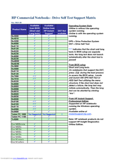
HP nx9000 - Notebook PC Product Support Bulletin (1 page)
Commercial Notebooks - Drive Self Test Support Matrix
Brand:
HP
| Category:
Laptop
| Size: 0.02 MB
Advertisement
Related Products
HP PAVILION NX9008
HP Compaq NX9005
HP nx9005 - Notebook PC
HP nx9008 - Notebook PC
HP Compaq NX9040
HP Compaq nx9010
HP nx9010 - Notebook PC
HP nx9020 - Notebook PC
HP nx9030 - Notebook PC
HP nx9040 - Notebook PC
HP Categories
Desktop
Laptop
Server
Monitor
Switch
More HP Manuals
Login
Sign In
OR
Sign in with Facebook
Sign in with Google
Upload manual
Upload from disk
Upload from URL