Sign In
Upload
Manuals
Brands
Motorola Manuals
Radio
M20KSS9PW1AN
Motorola M20KSS9PW1AN Manuals
Manuals and User Guides for Motorola M20KSS9PW1AN. We have
1
Motorola M20KSS9PW1AN manual available for free PDF download: Basic Service Manual
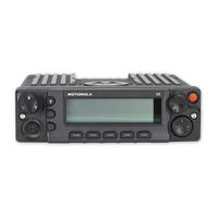
Motorola M20KSS9PW1AN Basic Service Manual (199 pages)
Digital Mobile Radio HF/UHF Range 1/UHF Range 2/ 700–800 MHz
Brand:
Motorola
| Category:
Radio
| Size: 33.42 MB
Table of Contents
Foreword
3
Manual Revisions
3
Computer Software Copyrights
3
Document Copyrights
3
Disclaimer
3
Trademarks
3
Document History
4
Table of Contents
6
Commercial Warranty
13
Limited Warranty
13
Motorola Communication Products
13
What this Warranty Covers and for How Long
13
II. General Provisions
13
III. State Law Rights
14
IV. How to Get Warranty Service
14
What this Warranty Does Not Cover
14
VI. Patent and Software Provisions
15
VII. Governing Law
15
Model Numbering, Charts, and Specifications
17
Mobile Radio Model Numbering Scheme
17
ASTRO XTL 5000 O3 VHF 10-50 Watt Model Chart
18
ASTRO XTL 5000 O3 VHF 10-50 Watt Model Chart (Cont.)
19
ASTRO XTL 5000 O3 VHF 100 Watt Model Chart
21
ASTRO XTL 5000 O3 VHF 100 Watt Model Chart (Cont.)
22
ASTRO XTL 5000 O3 UHF Range 1 10-40 Watt Model Chart
24
ASTRO XTL 5000 O3 UHF Range 1 10-40 Watt Model Chart (Cont.)
25
ASTRO XTL 5000 O3 UHF Range 1 100 Watt Model Chart
27
ASTRO XTL 5000 O3 UHF Range 1 100 Watt Model Chart (Cont.)
28
ASTRO XTL 5000 O3 UHF Range 2 10-40 Watt Model Chart
30
ASTRO XTL 5000 O3 UHF Range 2 10-40 Watt Model Chart (Cont.)
31
ASTRO XTL 5000 O3 700-800 Mhz 10-35 Watt Model Chart
33
ASTRO XTL 5000 O3 700-800 Mhz 10-35 Watt Model Chart (Cont.)
34
ASTRO XTL 5000 O3 700-800 Mhz 10-35 Watt (Reband) Model Chart
36
ASTRO XTL 5000 O3 700-800 Mhz 10-35 Watt (Reband) Model Chart (Cont.)
37
ASTRO XTL 5000 O5 VHF 10-50 Watt Model Chart
38
ASTRO XTL 5000 O5 VHF 10-50 Watt Model Chart (Cont.)
39
Figure 3-19. VHF Frequency Generation Unit Diagram
50
Figure 3-20. UHF Frequency Generation Unit Diagram
51
Figure 3-21. 700-800 Mhz Frequency Generation Unit Diagram
52
Table 4-1. Recommended Motorola Test Equipment
55
Table 4-2. Wattmeter Plug-In Elements
55
Table 4-3. Recommended Non-Motorola Test Equipment
56
Table 4-4. Service Aids for XTL 5000 Board-Level Troubleshooting
57
Table 4-5. Recommended Motorola Tools for Board-Level Troubleshooting
57
Table 4-6. Recommended Non-Motorola Tools for Board-Level Troubleshooting
58
Table 4-7. XTL 5000 Radio Field-Programming Items
58
Figure 5-1. Performance Checks Test Setup
59
Table 5-1. Test-Mode Displays
60
Table 5-2. Test Frequencies
61
Table 5-3. Signaling Types
62
Figure 5-2. XTL 5000 O3 Control Head
63
Figure 5-3. XTL 5000 Control Head
64
Table 5-4. Receiver Performance Checks
64
Table 5-5. Transmitter Performance Checks
65
Figure 6-1. Radio Alignment Test Setup
67
Figure 6-2. VHF/700-800 Mhz Tuner Main Menu
68
Figure 6-3. UHF Tuner Main Menu
68
Figure 6-4. Radio Information Screen
69
Table 6-1. PA Bias 1 Alignment RF Power Amplifier Devices
69
Figure 6-5. PA Bias 1 Alignment Screen
70
Table 6-2. Power Supply Voltage Settings
70
Table 6-3. PA Bias 1 Alignment Device Bias Current
70
Table 6-4. PA Bias 2 Alignment Amplifier Devices
71
Figure 6-6. PA Bias 2 Alignment Screen
72
Table 6-6. PA Bias 2 Alignment Device Bias Current
72
Figure 6-7. PA Bias 3 Alignment Screen
73
Table 6-7. PA Bias 3 Alignment Amplifier Devices
73
Table 6-9. PA Bias 3 Alignment Device Bias Current
74
Figure 6-8. Reference Oscillator Window
75
Table 6-10. Reference Oscillator Alignment
75
Table 6-5. Power Supply Voltage Settings
76
Figure 6-9. Power Detection Calibration Alignment Screen
77
Table 6-12. Power Supply Voltage Settings
77
Figure 6-10. Tx Power Characterization Alignment Screen
78
Table 6-8. Power Supply Voltage Settings
79
Figure 6-11. Tx Current Limit Alignment Screen
80
Table 6-14. Transmit Current Limit Offset
81
Table 6-15. Transmit Current Limit Devices
81
Figure 6-12. Tx Deviation Balance (Compensation) Alignment Screen
82
Figure 6-13. Tx Deviation Limit Alignment Screen
84
Figure 6-14. Rx Front-End Filter Alignment Screen
85
Figure 6-15. Bit Error Rate Screen
86
Table 6-16. Bit Error Rate Test Fields
86
Figure 6-16. Transmitter Test Pattern Screen
87
Table 6-17. Transmitter Test Pattern Fields
87
Table 7-1. UCM Kit Listing
89
Table 7-2. Secure Interface Board Kits
90
Table 8-1. Required Tools and Supplies
95
Figure 8-1. Cable Lock Detachment
96
Figure 8-2. Front Housing and Back Housing Detachment
97
Figure 8-3. Separate Front Housing and Back Housing
97
Figure 8-4. PCB Detachment
98
Figure 8-5. Disconnecting the 2-Pin Connector
98
Figure 8-6. Control Head Screw Sequence
99
Figure 8-7. Front Panel Disassembly
101
Figure 8-8. TUC Seal Placement
102
Figure 8-9. Front Panel Reassembly
103
Figure 8-10. Removing the Control Head Screws
104
Figure 8-11. Removing the Control Head
104
Figure 8-12. Removing the Flex (Control Head Connector)
105
Figure 8-13. Removing the Headbridge
105
Figure 8-14. Removing the Flex (Main-Board Connector)
106
Figure 8-15. Removing the Headbridge Seal
106
Figure 8-16. Removing the Secure Interface Board
107
Figure 8-17. Removing the Top Cover Screws
108
Figure 8-18. Lifting the Top Cover
108
Figure 8-19. Removing the J2 Rear Accessory Flex from the Main Board
109
Figure 8-20. Removing the PA Screws
110
Figure 8-21. Removing the RF/DC Retention Clips
110
Figure 8-22. Pushing up the Main Board
111
Figure 8-23. Removing the J2 Rear Accessory Connector
111
Figure 8-24. Removing the Transceiver Interface Board Screws
112
Figure 8-25. Removing the Transceiver Interface Board Assembly
113
Figure 8-26. Removing the Flex (Transceiver Interface Board Connector)
113
Figure 8-27. Removing the Flex (Main-Board Connector)
114
Figure 8-28. Removing the Front Panel Seal
114
Figure 8-29. Removing the Secure Interface Board
115
Figure 8-30. Removing the Top Cover Screws
116
Figure 8-31. Lifting the Top Cover
116
Figure 8-32. Removing the PA Screws
117
Figure 8-33. Removing the RF/DC Retention Clips
117
Figure 8-34. Pushing up the Main Board
118
Figure 8-35. Inspecting the Chassis Shield Gasketing and Thermal Pads
119
Figure 8-36. Inserting the J2 Rear Accessory Connector
120
Figure 8-37. Inserting the Main Board into the Chassis
121
Figure 8-38. Connecting the J2 Rear Accessory Connector Flex to the Main Board
122
Figure 8-39. Inserting the RF/DC Retention Clips
123
Figure 8-40. Inserting the RF/DC Retention Clip (DC Side)
123
Figure 8-41. Installing the PA Screws
124
Figure 8-42. Inspecting the Thermal Pad and Installing the Cover Main Seal
124
Figure 8-43. Securing the Top Cover to the Chassis
125
Figure 8-44. Installing the Secure Interface Board
126
Figure 8-45. Installing the Headbridge Seal
126
Figure 8-46. Installing the Control Head Flex in the Transceiver
127
Figure 8-47. Installing the Headbridge on the Transceiver
127
Figure 8-48. Installing the Control Head Flex on the Control Head
128
Figure 8-49. Inserting the Control Head into the Transceiver
128
Figure 8-50. Installing the Control Head Screws
129
Figure 8-51. Inspecting the Chassis Shield Gasketing and Thermal Pads
129
Figure 8-52. Inserting the Main Board into the Chassis
130
Figure 8-53. Inserting the RF/DC Retention Clips
130
Figure 8-54. Inserting the RF/DC Retention Clip (DC Side)
131
Figure 8-55. Installing the PA Screws
131
Figure 8-56. Inspecting the Thermal Pad and Installing the Cover Main Seal
132
Figure 8-57. Installing the Secure Interface Board
133
Figure 8-58. Installing the Front Panel Seal
133
Figure 8-59. Installing the TIB Flex in the Transceiver
134
Figure 8-60. Installing the Transceiver Interface Board Assembly Screws
134
Figure 8-61. Chassis Thermal Pad Locations
135
Table 8-2. Chassis Thermal Pad Parts
135
Figure 8-62. Chassis Thermal Pad Locations
137
Table 8-3. Chassis Thermal Pad Parts
137
Table 8-4. Fastener Torque Chart
138
Figure 9-1. GCAI Connector
139
Table 9-1. GCAI Connector Signal Descriptions
140
Figure 9-2. J2 Rear Accessory Connector
141
Table 9-2. J2 Rear Accessory Connector Signal and Voltage Descriptions
141
Figure 9-3. J100 Mobile Accessory Port (MAP) Connector
143
Table 9-3. J100 Remote Mount Control Head Mobile Accessory Port (MAP)
143
Figure 9-4. J200 Power and Audio Connector
145
Table 9-4. J200 Power and Audio Connector Pin Functions
145
Figure 9-5. J300 Controller Area Network (CAN) Connector on CHIB
146
Table 9-5. J300 Controller Area Network Connector Pin Functions
146
Figure 9-6. J400 VIP and DEK Connector
147
Table 9-6. J400 VIP and DEK Connector Functionality
147
Figure 9-7. J500 USB Host Connector
148
Table 9-7. J500 USB Host Connector
148
Figure 9-8. J600 Connector
149
Table 9-8. J600 Remote Mount Accessory Connector
149
Figure 9-9. J700 GCAI Programming Connector
151
Figure 9-10. J800 Controller Area Network (CAN) Connector on TIB
151
Table 9-9. J800 Controller Area Network Connector Pin Functions
151
Figure 9-11. RS232 Connector Naming Scheme
152
Table 9-10. Power-Up Error Codes
154
Table 9-11. Operational Error Codes
155
Table 9-12. Transmitter Troubleshooting Chart
156
Table 9-13. Receiver Troubleshooting Chart
157
Figure 10-1. XTL 5000 Transceiver Functional Block Diagram
159
Figure 10-2. XTL 5000 O3 Dash and Remote Control Head Functional Block Diagram
159
Figure 10-3. XTL 5000 O5 Dash and Remote Control Head Functional Block Diagram
159
Table 10-1. Table of Functional Block Diagrams and Connectors
159
Figure 10-4. XTL 5000 O3 Control Head Functional Block Diagram
163
Figure 10-5. XTL 5000 O5 Control Head Functional Block Diagram
164
Figure 10-6. XTL 5000 O5 Control Head Interface Board (CHIB) Functional Block Diagram
165
Figure 10-7. XTL 5000 Transceiver Interface Board (TIB) Functional Block Diagram
165
Figure 10-8. O3 Dash-Mount Radio Connector Locations (MID Power Only)
166
Figure 10-9. O3 Remote-Mount Radio Connector Locations
166
Figure 10-10.O3 Remote-Mount Radio Connector Locations (High Power Only)
166
Figure 10-11.O5 Dash-Mount Radio Connector Locations (MID Power Only)
167
Figure 10-12.O5 Remote-Mount Radio Connector Locations (MID Power Only)
167
Figure 10-13.O5 Remote-Mount Radio Connector Locations (High Power Only)
167
Figure 10-14.Main Board Connector Locations - Side 1 (MID Power Only)
168
Figure 10-15.Main Board Connector Locations - Side 2 (MID Power Only)
168
Figure 10-16.Main Board Connector Locations - Side 1 (High Power Only)
168
Figure 10-17.Main Board Connector Locations - Side 2 (High Power Only)
168
Figure 10-18.Control Head 50-Pin Connector
169
Figure 10-19.Control Head 60-Pin Connector
169
Table 11-1. Table of Exploded Views
171
Figure 11-1. XTL 5000 O3 Control Head Exploded View
172
Table 11-2. XTL 5000 O3 Control Head Parts List
172
Figure 11-2. XTL 5000 O5 Control Head Exploded View
173
Table 11-3. XTL 5000 O5 Control Head Parts List
173
Figure 11-3. CHIB and CHUC Exploded View
174
Table 11-4. CHIB and CHUC Parts List
174
Figure 11-4. Transceiver Interface Board (TIB) Exploded View
175
Table 11-5. Transceiver Interface Board (TIB) Parts List
175
Figure 11-5. XTL 5000 O3 Radio Exploded View
176
Table 11-6. XTL 5000 Dash Mount Radio Parts List
176
Figure 11-6. XTL 5000 O5 Dash Mount Radio Exploded View
177
Table 11-7. XTL 5000 Dash Mount Radio Parts List
177
Figure 11-7. XTL 5000 O5 MID Power Remote Mount Radio Exploded View
178
Table 11-8. XTL 5000 MID Power Remote Mount Radio Parts List
178
Figure 11-8. XTL 5000 100 W Remote Mount Radio Exploded View
179
Table 11-9. XTL 5000 100 W Remote Mount Radio Parts List
179
Advertisement
Advertisement
Related Products
Motorola Radius m200
Motorola M20KTS9PW1AN
Motorola M20QSS9PW1AN
Motorola M20QTS9PW1AN
Motorola M20SSS9PW1AN
Motorola M20URS9PW1AN
Motorola M20KSM9PW1AN
Motorola M20KTM9PW1AN
Motorola M20QSM9PW1AN
Motorola MagOne
Motorola Categories
Cell Phone
Two-Way Radio
Baby Monitor
Cordless Telephone
Radio
More Motorola Manuals
Login
Sign In
OR
Sign in with Facebook
Sign in with Google
Upload manual
Upload from disk
Upload from URL