Sign In
Upload
Manuals
Brands
Toro Manuals
Tractor
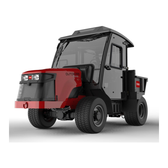
Outcross 9060
Toro Outcross 9060 Manuals
Manuals and User Guides for Toro Outcross 9060. We have
1
Toro Outcross 9060 manual available for free PDF download: Service Manual
Toro Outcross 9060 Service Manual (384 pages)
Brand:
Toro
| Category:
Tractor
| Size: 27.78 MB
Table of Contents
Table of Contents
7
Chapter 1 :Safety
10
Safety Instructions
10
Supervisor's Responsibilities
10
Before Operating the Machine
11
Operating the Machine
12
Maintenance and Service
14
Jacking Instructions
16
Raising the Front of the Machine
16
Safety and Instructional Decals
17
Raising the Rear of the Machine
17
Chapter 2: Specifications and Maintenance
19
Specifications
20
Overall Dimensions
20
Traction Unit
21
Engine
21
Hydraulic System
22
Traction and PTO Drive
22
Chassis
23
Torque Specifications
24
Calculating the Torque Values When Using a Drive-Adapter Wrench
25
Identifying the Fastener
26
Standard Torque for Dry, Zinc Plated, and Steel Fasteners (Inch Series)
27
Standard Torque for Dry, Zinc Plated, and Steel Fasteners (Metric Fasteners)
28
Other Torque Specifications
29
Conversion Factors
29
Shop Supplies
30
Special Tools
32
Chapter 3: Troubleshooting
39
GEARS - the Systematic Approach to Defining, Diagnosing and Solving Problems
40
Gather Information
40
Evaluate Potential Causes
40
Assess Performance
40
Repair
40
Solution Confirmation
40
Operator Advisories
41
Machine and Engine Faults
44
Using the Infocenter Display for Troubleshooting
61
TRACTION (Example)
61
General Hydraulic System Problems
64
Traction System Problems
65
Steering System Problems
68
PTO System Problems
69
3-Point Hitch System Problems
70
Attachment/Loader Problems
71
General Information/Service and Repairs
73
General Information
74
Traction Unit Operator's Manual
74
Yanmar Service and Troubleshooting Manuals
74
Shutting off the Engine
74
Chapter 4: Engine
75
General Information
75
Engine Electronic Control Unit (ECU)
75
Yanmar Engine
76
Diesel Particulate Filter
77
Service and Repairs
80
Air Cleaner System
80
Exhaust System
82
Radiator
83
Fuel System
86
Engine
89
Flywheel Housing and Drive Coupler
95
Chapter 5: Hydraulic System
97
General Information
99
Traction Unit Operator's Manual and Accessory Installation Instructions
99
Relieving Pressure from the Hydraulic System
99
Towing the Traction Unit
100
Traction Circuit (Closed-Loop) Component Failure
102
Hydraulic Hoses
103
Installing Hydraulic Hoses and Tubes (O-Ring Face Seal)
104
Installing the Hydraulic Fittings (SAE Straight Thread O-Ring Fittings)
106
Hydraulic Schematic
109
Hydraulic Flow Diagrams
110
Traction Circuit
110
Steering Circuit
114
Hitch Cylinder Circuit
118
Brake Circuit
121
Differential Lock Circuit
122
PTO Clutch Circuit
124
Attachment Circuit
126
Front Loader Circuit
127
Selector Control Valve (SCV) Circuit (Optional)
129
Testing the Hydraulic System
130
Hydraulic Test Selection
133
Traction Circuit Testing - Charge Pressure Test
133
Traction Circuit Testing - Traction Pump (P1) and (P2) Flow and Relief Valve Tests
133
Steering/Hitch Cylinder Circuit Testing - Steering Relief Valve (RV1) Pressure Test
134
Steering/Hitch Cylinder Circuit Testing - Hitch Cylinder Test
136
Steering/Hitch Cylinder Circuit Testing - Hitch Cylinder Relief Valve (RV2) Pressure Test
137
Steering/Hitch Cylinder Circuit Testing - Gear Pump (P4) Flow Test
139
Attachment/Loader Circuit Testing - Relief Valve Pressure Test
139
Attachment/Loader Circuit Testing - Gear Pump (P3) Flow Test
141
Adjustments
144
Adjusting the Manifold Relief Valves
144
Service and Repairs
145
General Precautions for Removing and Installing the Hydraulic System Components
145
Checking the Hydraulic Lines and Hoses
147
Flushing the Hydraulic System
148
Filtering the Closed-Loop Traction Circuit
150
Priming the Hydraulic Pumps
154
Charging the Hydraulic System
155
Hydraulic Tank
157
Hydraulic Fluid Cooler
159
Tandem Piston (Traction) Pump (P1) and (P2)
160
Tandem Piston (Traction) Pump (P1) and (P2) Service
164
Gear Pump (P3) and (P4)
166
Gear Pump (P3) and (P4) Service
168
Axle Motors
172
Axle Motor Service
174
Axle Differential Locks
175
Hydraulic Brake Assembly
176
Hydraulic Brake Service
178
Main Hydraulic Manifold
180
Main Manifold Service
182
Cartridge Valve Service
184
Steering Control Valve
186
Steering Control Valve Service
188
Steering Cylinders
189
Steering Cylinder Service
191
3-Point Hitch Cylinders
194
3-Point Hitch Cylinder Service
196
PTO Clutch
198
Auxiliary Load Valve
199
Auxiliary Load Valve Service
201
Front Loader Control Valve
202
Front Loader Control Valve Service
204
Selector Control Valve Manifolds (Optional)
205
Selector Control Valve Manifold (Optional) Service
207
Chapter 6: Electrical System
209
General Information
211
Traction Unit Operator's Manual and Accessory Installation Instructions
211
Yanmar Engine Electrical Components
211
Infocenter Display
212
Primary Controller (T1: TEC)
214
Status Display Controller (T2: TDM)
215
Engine Electronic Control Unit (ECU)
217
Inchmode Controller (T3: TEC) (Optional)
218
Can−Bus Communications
219
Electrical Drawings
220
Electrical System Quick Checks
221
Testing the Charging System
221
Checking the Operation of the Interlock Switches
221
Electrical Component Testing
222
Fuses
222
Fusible Link Harness
225
CAN Bus
226
Primary Controller (T1: TEC)
227
Status Display Controller (T2: TDM)
230
Inchmode Controller (T3: TEC) (Optional)
233
Key Switch
235
Mode Selector
236
Parking Brake Switch
237
Power Take off (PTO) Enable Switch
238
Economy (ECO) Mode Switch
239
Hydraulic Auxiliary (AUX) Switch
240
Seat Switch
242
Paddle (3-Point Hitch) and Transmission Lever Switches
243
Headlight/Worklight Switch
245
Cruise Control Off/On/Set Switch
246
Cruise Control Speed Increase/Decrease Switch
247
Air Conditioning On/Off Switch
248
Heater/Air Conditioning Blower Speed Switch
249
Inchmode Enable Switch (Optional)
250
Inchmode Raise/Lower and Forward/Reverse Switches (Optional)
251
Loader Selector Control Valve (SCV) Switch (Optional)
252
Traction Pedal Assembly
253
Decelerator Pedal Position Sensor
255
Decelerator Pedal Neutral Switch
257
3-Point Hitch Position Sensor
259
Hydraulic Fluid Temperature Sender
261
Speed Sensors
263
Traction Pressure Sensors
265
Fuel Pump
267
Fuel Level Sender
269
Warning Buzzer
270
Relays with 4 Terminals
271
Relays with 5 Terminals
273
Diode Assemblies
277
Resistor Assembly
278
CAN-Bus Terminator Resistors
279
Hydraulic Solenoid Valve Coils
281
Tandem Traction (Piston) Pump Control Solenoid Coils
283
Caring for the Battery
285
Service and Repairs
285
Storing the Battery
287
Servicing the Battery
288
Chapter 7 Traction and Pto Drive
295
General Information
296
Traction Unit Operator's Manual and Accessory Installation Instructions
296
Adjustments
297
Adjusting the Tie Rod Length
297
Adjusting Axle Stop Bolts
297
Service and Repairs
299
Tie Rods
299
Front Axle
301
Rear Axle
304
Front and Rear Axle Service
307
Front PTO Gear Box
308
PTO Clutch
313
Rear PTO Gear Box
315
PTO Drive Shaft
318
General Information/Service and Repairs
321
Chapter 8 :Chassis
322
General Information
322
Traction Unit Operator's Manual and Accessory Installation Instructions
322
Service and Repairs
323
Front Screen
323
Hood
324
Operator Platform
326
Steering Wheel, Instrument Panels and Dash Cover
335
Operator's Console
337
Seats
338
Standard Bed
341
Front Loader Attachment
342
Table of Contents
343
Chapter 9 :Operatorcab
344
General Information
344
Traction Unit Operator's Manual and Accessory Installation Instructions
344
Electrical Components, Schematics and Wire Harness Drawings
344
Air Conditioning System
345
Cab Heater System
346
Adjustments
347
Adjusting the Compressor Belt Tension
347
Adjusting the Doors
348
Service and Repairs
349
General Precautions for Removing and Installing Air Conditioning System Components
349
Air Conditioning Compressor
351
Heating and Air Conditioning Components
353
Control Panel and Windshield Wiper Assembly
354
Doors
357
Appendix A
359
Electrical Drawing Designations
360
Hydraulic Schematic
361
Electrical Schematic (Part 1
362
Electrical Schematic (Part 2
363
Electrical Schematic (Part 3
364
Wire Harness Drawing - Frame
365
Wire Harness Diagram - Frame
366
Wire Harness Drawing - Platform
367
Wire Harness Diagram - Platform
368
Wire Harness Diagram - Platform (Continued
369
Wire Harness Drawing - Engine
370
Wire Harness Diagram - Engine
371
Wire Harness - Headlights
372
Wire Harness - Cab Rooftop
373
Wire Harness - Cab Control Panel
374
Wire Harness - Cab Heat/Air Conditioning
375
Wire Harness - Inchmode (Optional
376
Wire Harness - Loader Selector Control Valve (SCV) Switch (Optional)
377
Wire Harness - Loader Selector Control Valve (SCV) Valve (Optional)
378
Wire Harness - Rear Selector Control Valve (SCV) Kit (Optional
379
Wire Harness - Cab Work Light Kit (Optional
380
Wire Harness - Domestic Road Light Kit (Optional
381
Wire Harness - Turn Signal/Hazard Lights (Optional
382
Wire Harness - International Road Light Kit (Optional
383
Advertisement
Advertisement
Related Products
Toro Outcross 9060 Series
Toro 900 Series
Toro 9200
Toro Power Max 926 OXE
Toro Air Cool Z Master 96in 74090
Toro 99251
Toro 999999999
Toro 990001
Toro 97772
Toro 03678
Toro Categories
Lawn Mower
Lawn Mower Accessories
Snow Blower
Lawn and Garden Equipment
Utility Vehicle
More Toro Manuals
Login
Sign In
OR
Sign in with Facebook
Sign in with Google
Upload manual
Upload from disk
Upload from URL