Advertisement
Advertisement
Table of Contents

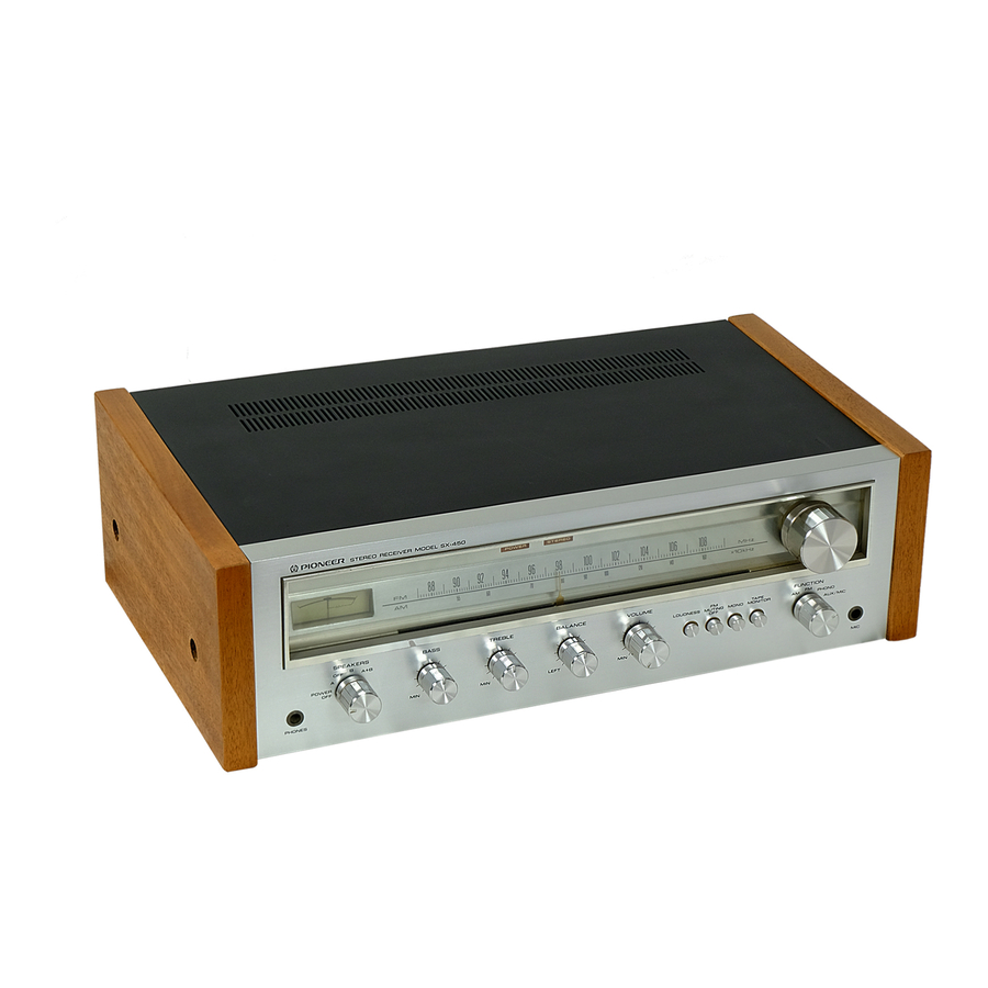
Summary of Contents for Pioneer sx-450
- Page 1 3s=r--*-** *':* o-si' €I -iiJ\ (0rrroruEen...
-
Page 2: Wiring Diagram
AM /FN STEREO RECEIUER 0,o3 2SC+61 lu,Quz2SA?25 xz & S W I T C H I S ; SPEAKER S P O W E R O F F S P A S P O F F zo{ 2scl222xz ozor , ( q 2SCt 222 M O D E STEREO +---_ l'10N0... - Page 3 RF Asst AwE o,orHAlll3? Cr1.0.4'/:S Cw\.41hs 2SCl222 xz -t=fr :< C W . t . e t " 5 = - F tar i- ) < , ' r t l u C2a6 C.O I VR l BALAN C E CONTROL 1tl(85) STEREO INO...
- Page 4 ,PLS &., q J t Cmz. Crro a - a + ^ + a > o , -+' 2SCl3 8/|. Dror,ft12 Qror Rlor 33 93_or FU ocor250313R .<r- t r r . v l UXos - UIOB U3o8 DIAL INDICATOR E V 3 0 0 m A x 3 ASs'y AWK - 009 2s c I gt gn"...
- Page 5 :< shs'1i++ > - + ' zSCl3 8+ Dor,D312 lOE 2 xe Qror Broijf 9qo' _FU: q3o,250313R v> . i v . v t Ujos ! U30t U3o6 DIAL INDICATOR 8 V 3 0 0 m A x 3 A S s ' y AWK - 069 Qo,r,Qos 2SCl3tSAxz 2g\ltQlxz ,0.6V...
- Page 6 RF Ass'/ AWE o, HA1.l37 <: Rzia iOoir REC- i l'10Nlr0R VI : SIONAL VOLTAGE AT E A K E R O U T P U T 1 0 . 9 V / E Q ( l K H r ) G mA : DC CURRENT AT NO V : DC VOLTAGE AT NO...
- Page 7 VCrlCr C,n4 P1'-Jlc-'-#lF ll;ia )< 0,03 2SC+61 LA vc, rct la,Qnz2SA?25 xz ozo3, 2SCt 222 S W I T C H E S ; SPEAKER S P O W E R O F F S P A S P O F F F M M U T I N G 0N -'t F U N C T | 0 N...
- Page 8 Set AM signal generator and SX-450 dial in- dication to point C (1,400kH2). 7. Adjust TC4 for maximum indication on AC voltmeter. 8. Again set AM signal generator and SX-450 dial indication to point A. 9. Adjust bar antenna core for maximum in- dication on AC voltmeter.
- Page 9 C (106MHz). 9. Adjust TC3, then TC1 and TC2 for *u"i*rr- indication on AC voltmeter. 10. Again set FM signal generator and SX-450 dial indication to point A. 11. Adjust T3, then T1 and T2 for maximum indication on AC voltmeter.
- Page 10 TP (No. 13) of circuit board. r | } 4. Set SX-450 dial indication to 98MHz and adjust FM signal generator for center of scale indi- cation on AM/FM meter. 5. With FM signal generator unmodulated, adjust VR1 so that lissajous pattern on oscilloscope becomes stationary as shown in Fig.
- Page 11 1. Set BASS and TREBLE controls ro center position. 2. Nothing should be connected to the INPUT jacks of SX-450 and an 8 ohm dummy load should be connected across the SPEAKER terminal. 3. A DC voltmeter should be connect across between terminal number 19 1+;, 20 (-)
- Page 12 . . ' P u l l e y C Stud Start: Fasten on end of the cord to start sx-450 D i a l n e e d l e ' r l F i s . 1 3...


