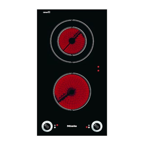
Miele KM 400 Installation Instructions Manual
Ceramic hobs ceramic contact grill open grill deep fat fryer
Hide thumbs
Also See for KM 400:
- Operating instructions manual (28 pages) ,
- Installation instructions manual (16 pages) ,
- Dimension manual (1 page)
Table of Contents
Advertisement
Installation Instructions
Ceramic hobs
KM 400 / 400-3 / 412 / 418 / 418-1
Ceramic contact grill
KM 408-1 / 408-2
Open grill KM 410 / 411 / 411-3
Deep fat fryer KM 402 / 403
en - GB
To avoid the risk of accidents
or damage to the machine
it is essential to read these
instructions before it is
installed and used for the first time.
M.-Nr. 04 930 397
Advertisement
Table of Contents

Summary of Contents for Miele KM 400
-
Page 1: Installation Instructions
Installation Instructions Ceramic hobs KM 400 / 400-3 / 412 / 418 / 418-1 Ceramic contact grill KM 408-1 / 408-2 Open grill KM 410 / 411 / 411-3 Deep fat fryer KM 402 / 403 en - GB To avoid the risk of accidents... -
Page 2: Table Of Contents
Appliance dimensions ..........6 KM 400 / KM 400-3 / KM 408-1 / KM 408-2 / KM 412 ..... . . 6 KM 402 / KM 403 . -
Page 3: Warning And Safety Instructions
40 mm = KM 400, 400-3, 402, 403, 412, 418, 418-1 50 mm = 408-1, 408-2 250 mm = KM 410, 411, 411-3... -
Page 4: Additional Safety Notes On Induction Hobs / Km 418 / Km 418-1
Warning and Safety instructions After installation of the hob ensure Additional safety notes on induction that the connection cable is without hobs / KM 418 / KM 418-1 hindrance and that there is no This hob must not be installed mechanical obstruction which could above an oven or cooker unless these damage it, such as a drawer. -
Page 5: Safety Distance Above The Appliance
Warning and Safety instructions Safety distance above the appliance Safety distance between the KM 410 / KM 411 / KM 411-3 and a cooker hood above it For safety reasons, the minimum safety distance between the KM410/ KM 411 / KM 411-3 Open grill and a cooker hood above it, is the same as for gas hobs, i.e. -
Page 6: Appliance Dimensions
Appliance dimensions KM 400 / KM 400-3 / KM 408-1 / KM 408-2 / KM 412 a Spring clamps Ensure that the connection cable cannot come into contact with the b Protective shelf underside of the appliance. (KM 408-1 / KM 408-2 only) - Page 7 Appliance dimensions KM 402 / KM 403 a Spring clamps b Drain tap...
- Page 8 Appliance dimensions KM 410 / KM 411 / KM 411-3 a Spring clamps b Drain tap...
- Page 9 Appliance dimensions KM 418 / KM 418-1 a Spring clamps b Building-in depth c Front d Building-in depth - mains connection box...
-
Page 10: Worktop Cut-Out
Worktop cut-out ^ Seal the cut surfaces with a suitable sealant to avoid swelling caused by moisture. The materials used must be heat resistant. Worktop cut-out Depth Width (=Dim. B) Number of in mm in mm appliances ± 1 mm ±... -
Page 11: Installation
Installation Fitting the spacer bars and spring clamps a Spring clamps c Gap between spacer bar and worktop b Spacer bars Installation of several appliances ^ Fix the spacer bars b and the spring clamps a provided to the positions The illustration above shows an example of a worktop cut-out with indicated. -
Page 12: Fixing The Spacer Bars
Installation Fixing the spacer bars Fixing the spring clamps ^ Position the spacer bars b in the ^ Position the spring clamps a in the positions shown in "Fitting the spacer positions shown in "Fitting the spacer bars and spring clamps" so they are bars and spring clamps"... -
Page 13: Building In The Appliance
Installation Building in the appliance ^ Guide the hob electric cable down through the cut-out and connect the appliance to the electricity supply. ^ Position the hob. Then with a hand on each side of the hob, press down on the fixing points of the spring clamps a on the top and bottom edges until it clicks into place. -
Page 14: General
General Important Under no circumstances should sealant find its way between the frame of the top part of the hob and the worktop. This could cause difficulties if the hob ever needs to be taken out for servicing, (possibly leading to damage to the frame and worktop). -
Page 15: Electrical Connection
Please contact be provided for all poles. the Miele Service / Spare Parts For extra safety it is advisable to install Department. a residual current device (RCD) with a trip current of 30 mA. - Page 16 Electrical connection Important The electrical safety of this appliance can only be guaranteed when continuity is complete between the appliance and an effective earthing system, which complies with local and national regulations. It is most important that this basic safety requirement is present and tested regularly and if there is any doubt the electrical wiring in the home should be inspected by a...
- Page 20 Alteration rights reserved / 3707 M.-Nr. 04 930 397 / 01...


