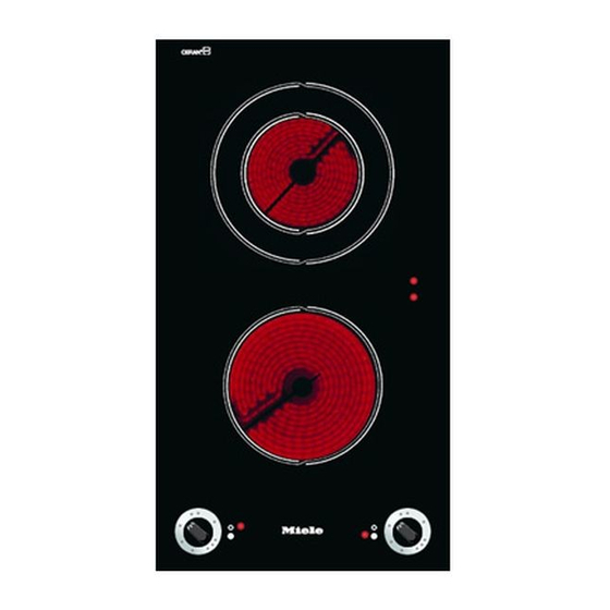
Miele KM 400 Installation Instructions Manual
Ceramic hobs; ceramic contact grill; open grill; deep fat fryer
Hide thumbs
Also See for KM 400:
- Technical information (66 pages) ,
- Operating instructions manual (24 pages) ,
- Product and cut-out dimensions (1 page)
Table of Contents
Advertisement
Installation Instructions
Ceramic hobs
KM 400 / KM 412 / KM 418
Ceramic contact grill KM 408-1
Open grill KM 410 / KM 411
Deep fat fryer KM 402 / KM 403
WO
It is essential to read these
instructions before installing
or using the machine, to avoid
the risk of accident or
damage to the machine.
M.-Nr. 05 021 213
Advertisement
Table of Contents

Summary of Contents for Miele KM 400
-
Page 1: Installation Instructions
Installation Instructions Ceramic hobs KM 400 / KM 412 / KM 418 Ceramic contact grill KM 408-1 Open grill KM 410 / KM 411 Deep fat fryer KM 402 / KM 403 It is essential to read these instructions before installing... -
Page 2: Table Of Contents
KM 400........ -
Page 3: Warning And Safety Instructions
KM 400, KM 402, KM 403, KM 412 KM 418 = 40 mm KM 408-1 = 50 mm KM 410 / KM 411 = 250 mm... -
Page 4: Additional Safety Notes On Induction Hobs / Km 418
Warning and Safety instructions After installation ensure that the Safety distance above the appliance connection cable is without hindrance and that there is no mechanical obstruction which could damage it, such as a drawer. These appliances must not be installed over a dishwasher, washing machine, tumble dryer, refrigerator, fridge-freezer or freezer. -
Page 5: Safety Distance Between The Km 410 / Km 411 And A Cooker Hood Above It
Warning and Safety instructions Safety distance between the KM 410 / All grease filters must be cleaned regularly and active charcoal filters KM 411 and a cooker hood above it replaced regularly. Fat build up in the For safety reasons, the minimum filters is a potential fire hazard. -
Page 6: Appliance Dimensions
Appliance dimensions KM 400 a Spring clamps... - Page 7 Appliance dimensions KM 408-1 / KM 412 a Spring clamps Ensure that the connection cable b Protective shelf (KM 408-1 only) cannot come into contact with the underside of the appliance. A protective shelf and a front panel A minimum distance of 80 mm is must be fitted underneath KM 408-1 required between the upper to ensure that the underside of the...
- Page 8 Appliance dimensions KM 402 / KM 403 a Spring clamps b Drain tap...
- Page 9 Appliance dimensions KM 410 / KM 411 a Spring clamps b Drain tap...
- Page 10 Appliance dimensions KM 418 a Spring clamps b Building in height c Front d Building in height including electrical connection box...
-
Page 11: Worktop Cut-Out
KM 400, KM 402, KM 403, KM 412 KM 418 = 40 mm KM 408-1 = 50 mm KM 410 / KM 411 = 250 mm See also chapter "Warning and Safety... -
Page 12: Installation
Installation Fitting the spacer bars and spring clamps a Spring clamps c Gap between spacer bar and worktop b Spacer bars Installation of several appliances ^ Fix the spacer bars b and the spring The illustration above shows an clamps a provided to the positions example of a worktop cut-out with indicated. -
Page 13: Fixing The Spacer Bars
Installation Fixing the spacer bars Fixing the spring clamps ^ Position the spacer bars b in the ^ Position the spring clamps a in the positions shown in "Fitting the spacer positions shown in "Fitting the spacer bars and spring clamps" so they are bars and spring clamps"... -
Page 14: Building In The Appliance
Installation Building in the appliance ^ Guide the hob electric cable down through the cut-out and connect the appliance to the electricity supply. ^ Position the hob. Then with a hand on each side of the hob, press down on the fixing points of the spring clamps a on the top and bottom edges until it clicks into place. -
Page 15: General
General Important Under no circumstances should sealant find its way between the frame of the top part of the hob and the worktop. This could cause difficulties if the hob ever needs to be taken out for servicing, (possibly leading to damage to the frame and worktop). -
Page 16: Electrical Connection
Electrical connection Important All electrical work should be carried The wires in the mains lead are out by a suitably qualified and coloured in accordance with the competent person in strict following code: accordance with national and local safety regulations. Green/yellow = earth Blue = neutral... - Page 20 Alteration rights reserved / 3905 M.-Nr. 05 021 213 / 02 en - AUS...


